

Dispersing device
A dispersing device and dispersing technology, applied in mixers with rotary stirring devices, transportation and packaging, mixers, etc., can solve the problems of reduced durability, difficult coating, and reduced dispersing ability, and achieve improved dispersing ability and durability. sexual effect
- Summary
- Abstract
- Description
- Claims
- Application Information
AI Technical Summary
Problems solved by technology
Method used
Image

Examples
no. 1 approach >
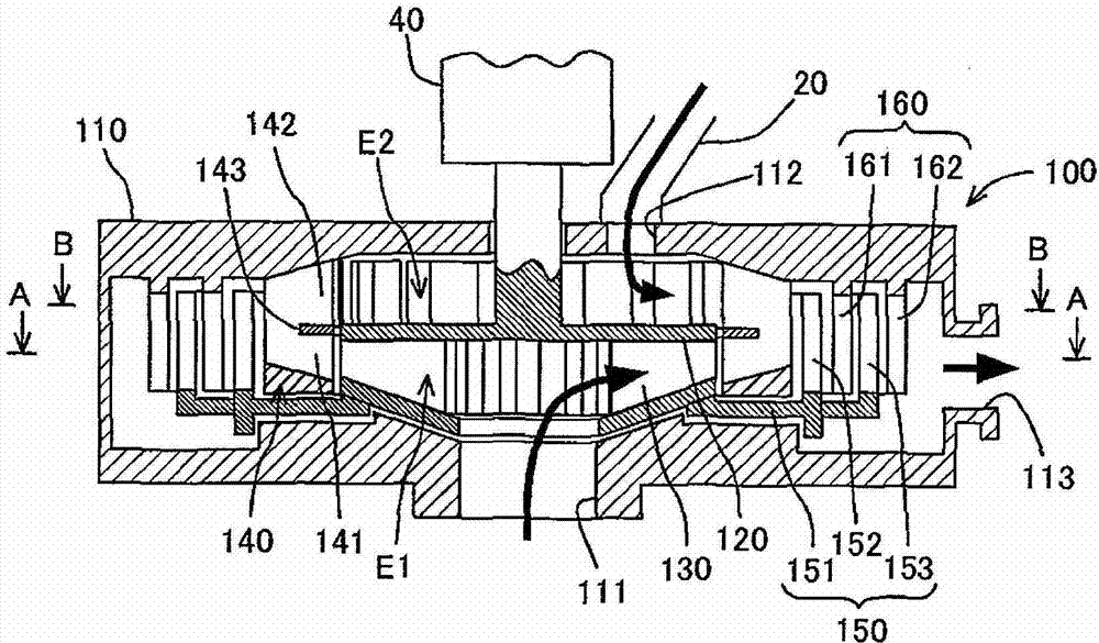
[0047] The mixing and dispersing apparatus of this embodiment constitutes an apparatus for manufacturing electrodes (positive and negative electrodes) of lithium ion secondary batteries, for example. A lithium ion secondary battery is molded by applying a slurry of an active material material to a base material such as aluminum foil or copper foil and firing it. The mixing and dispersing device of this embodiment is a device for producing a slurry of an active material material. Specifically, it is produced by mixing and dispersing metal powder of an active material in a liquid such as water. Hereinafter, the slurry after mixing and dispersing the powder material is called a fluid mixed material, and the liquid before mixing the powder material is called a fluid base material. Both the fluidity mixed material and the fluidity matrix material have fluidity. However, the fluid mixed material is formed to have a higher viscosity than the fluid base material.
[0048] refer to ...
no. 2 approach >
[0070] refer to Figure 8~9 The mixing and dispersing device of this embodiment will be described. In the mixing and dispersing device of the present embodiment, the first annular dispersing member 150 and the second annular dispersing member 160 in the mixing and dispersing device of the first embodiment are disposed on the downstream side of the rotating blade 130 in the axial direction relative to the rotating blade 130 different locations. Furthermore, the guide member 140 is replaced by the stator with holes 270 and the rotating outer blade 240 . Hereinafter, different points will be described, and here, components having the same structure or the same function will be denoted by the same reference numerals, and description will be omitted.
[0071] The device main body 200 includes a casing 110 , a partition plate 120 , a rotating vane 130 , a stator with holes 270 , a rotating outer vane 240 , a first annular dispersing member 150 , and a second annular dispersing mem...
no. 3 approach >
[0078] refer to Figure 10~12 The mixing and dispersing device of this embodiment will be described. In the mixing and dispersing device of the present embodiment, the protruding directions of the protruding teeth 152, 153, 161, and 162 of the first annular dispersing member 150 and the second annular dispersing member 160 in the mixing and dispersing device of the second embodiment are changed from the axial direction. is radial. Hereinafter, different points will be described, and here, components having the same structure or the same function will be denoted by the same reference numerals, and description will be omitted. Here, the mixing and dispersing device of this embodiment is arranged so that the direction of the rotation axis is the direction of gravity, Figure 10 The bottom of is the bottom of the gravity direction.
[0079] The first annular dispersing member 350 constituting the device main body 300 is disposed below the rotating blade 130 . The first annular...
PUM
 Abstract
Description
Claims
Application Information