
Grooving jig used for clamping synchronizer duplicate gear

A technology of double gears and synchronizers, applied in the direction of expanding the mandrel, can solve the problems of low positioning accuracy, poor clamping accuracy, complicated operation, etc., to achieve convenient installation and disassembly of gear blanks, overcome defects, and improve clamping accuracy. Effect

Active Publication Date: 2013-06-26
CHONGQING WINSTAR PRECISE MACHINERY
View PDF8 Cites 6 Cited by
  • Summary
  • Abstract
  • Description
  • Claims
  • Application Information

AI Technical Summary

Problems solved by technology

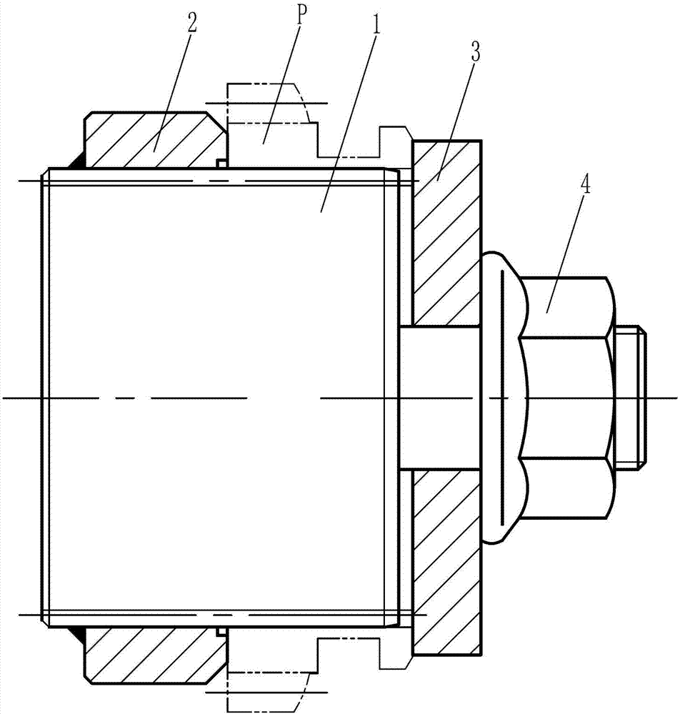
[0003] 1. Since the fixture shaft 1 positions the inner spline hole of the tooth blank P through its outer spline, the positioning accuracy is low, which leads to poor clamping accuracy;
[0004] 2. When installing the tooth blank P and removing the tooth blank P after processing, it is necessary to disassemble the washer 3 and the lock nut 4. The operation is complicated, time-consuming and laborious

Method used


Image

  • Grooving jig used for clamping synchronizer duplicate gear
  • Grooving jig used for clamping synchronizer duplicate gear

Examples


Embodiment Construction

[0019] Below in conjunction with accompanying drawing and embodiment the present invention will be further described:

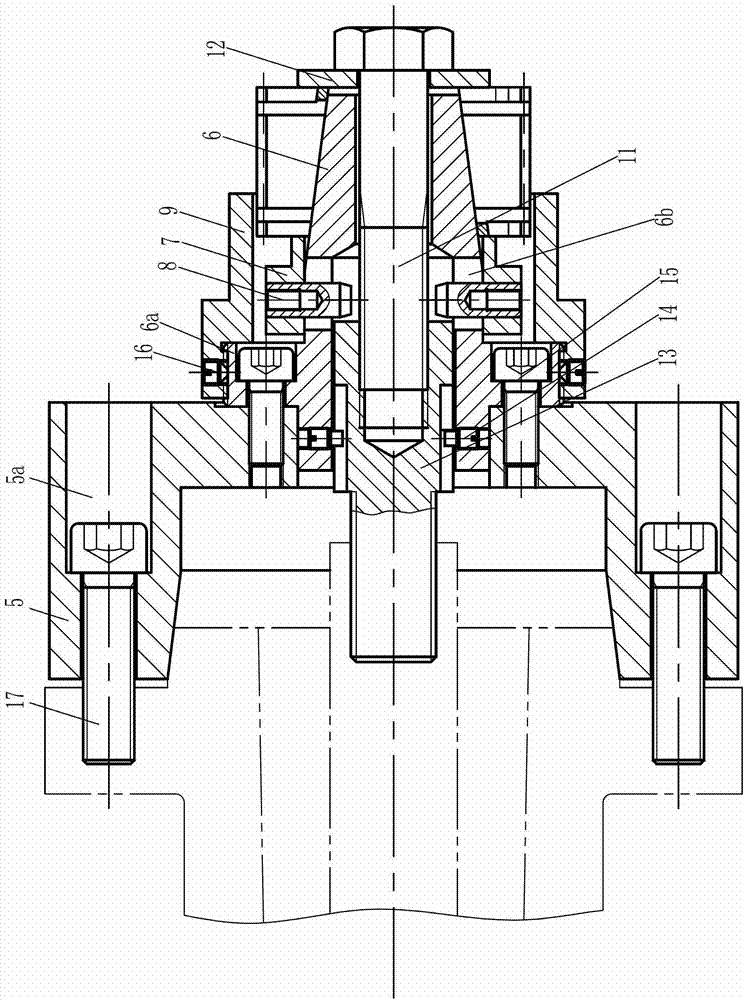
[0020] Such as figure 2 As shown, the present invention is mainly composed of connecting plate 5, mandrel 6, sliding sleeve 7, cylindrical pin 8, positioning sleeve 9, expansion sleeve 10, bolt 11, washer 12, pull rod 13, anti-rotation screw 14, screw 15 and taper end Set screw 16 constitutes. Wherein, a plurality of axial mounting holes 5a are opened on the connecting plate 5, and the connecting plate 5 is connected with the main shaft of the lathe through connecting screws 17 penetrated in the axial mounting holes 5a. The inner hole of the connection plate 5 is a two-stage stepped hole with a large diameter on the left and a small diameter on the right, wherein the left end surface of the large aperture section is a conical surface.

[0021] The axis line of the mandrel 6 is on the same straight line as the axis line of the connection plate 5, the left e...


PUM


Abstract

The invention discloses a grooving jig used for clamping a synchronizer duplicate gear. The left end of a mandrel is inserted into a small diameter section of an inner hole of a connecting plate, and an annular installing boss on the left end portion of the mandrel is fixed with the connecting plate; a sliding sleeve is coaxially sleeved on the middle portion of the mandrel, a cylindrical pin is connected in a radial hole formed in the sliding sleeve, and the inner end of the cylindrical pin stretches into a center hole of the mandrel after penetrating through a strip-shaped sliding hole formed in the mandrel; a positioning sleeve is sleeved outside the sliding sleeve, and the left portion of the positioning sleeve is fixed with the annular installing boss; the right portion of the mandrel is a conical part with the left big and the right small, an expansion sleeve is sleeved on the right portion of the mandrel, a conical inner hole of the expansion sleeve is matched with the conical part of the mandrel, axial grooves are formed in the left portion of the expansion sleeve along the circumferential direction, and external splines are arranged on the positions, between every two adjacent axial grooves, of the expansion sleeve; after a washer is sleeved on the rod portion of a bolt, the rod portion of the bolt is inserted into the center hole of the mandrel and connected with an inner thread hole formed in the right end portion of a draw bar; and the draw bar is located on the left side of the cylindrical pin, and an outer thread section of the left portion of the draw bar stretches into a large hole diameter section of the inner hole of the connecting plate. Inner spline holes of gear blanks are positioned through the expansion sleeve, the expansion sleeve is even in deformation in the peripheral direction, the clamping precision can be thus improved, the jig can be used for installing and detaching gears very conveniently, and therefore shortcomings of a traditional grooving jig are effectively overcome.

Description

technical field [0001] The invention belongs to the field of clamps, and in particular relates to a slotting clamp for clamping a double gear of a synchronizer. Background technique [0002] The double gear is an important part of the synchronizer, and its inner hole is often a spline hole. At present, we often use lathes to process the annular groove in the middle of the synchronizer duplex gear. figure 1 The grooving fixture shown is used to clamp the tooth blank P of the gear. The grooving fixture includes a fixture shaft 1. The fixture shaft 1 is a two-stage stepped structure with a large left side and a small right side. The large diameter section is provided with external splines. And at the left end of the large-diameter section, a positioning connection sleeve 2 is arranged through welding, and the positioning connection sleeve 2 is clamped by the three-jaw chuck of the lathe during installation. The small-diameter end of the clamp shaft 1 is sequentially fitted wi...

Claims


Application Information

Patent Timeline
Patent Type & Authority Applications(China)
IPC IPC(8): B23B31/40
Inventor 段含辉
Owner CHONGQING WINSTAR PRECISE MACHINERY
Learn More