Working medium internal combustion heater

A technology of internal combustion heaters and working fluids, which is applied in the direction of machines/engines, hot gas variable displacement engine devices, mechanical equipment, etc., and can solve problems affecting stable work, fluctuations in injection status, displacement of mixing areas, etc., and achieve stable work.

Active Publication Date: 2013-06-26
山东沃达纸制品有限公司
View PDF5 Cites 3 Cited by
  • Summary
  • Abstract
  • Description
  • Claims
  • Application Information

AI Technical Summary

Problems solved by technology

[0002] When it is necessary to fully mix a fluid with the reciprocating fluid in the working medium envelope, or fully mix and undergo a chemical reaction (such as fully mixed combustion), the fluid is usually injected directly into the working medium envelope, which This method will not only cause fluctuations in the injection state, but also cause displacement of the mixing zone (chemical reaction zone), which will affect stable work

Method used


Image

  • Working medium internal combustion heater
  • Working medium internal combustion heater
  • Working medium internal combustion heater

Examples


Embodiment 1

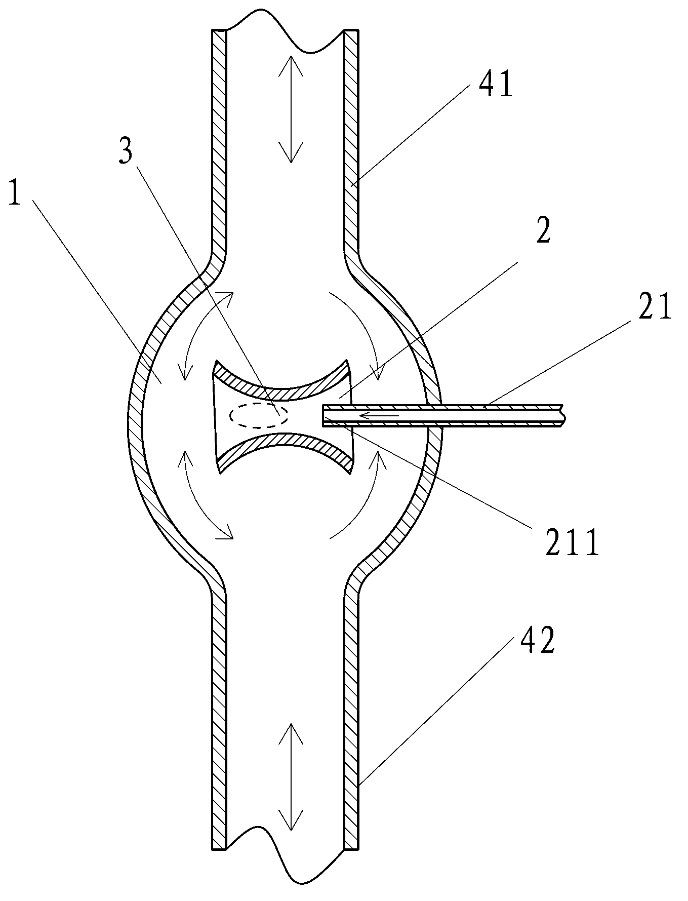
[0033] Such as figure 1 The shown working medium internal combustion heater includes a working medium enveloping space 1, a jet pump 2 and a combustion chamber 3. The working medium enveloping space 1 is composed of a reciprocating channel 41 and a reciprocating channel 42, and the jet pump 2 is located at In the working medium envelope space 1, the high-pressure power fluid nozzle 211 on the jet pump 2 communicates with the oxidant source and the reductant source, and the combustion chamber 3 is arranged between the fluid outlet of the jet pump 2 and the jet between the high-pressure power fluid nozzles 211 of the pump 2.

[0034] As an alternative implementation, the high-pressure power fluid nozzle 211 on the jet pump 2 can be changed to communicate with one of the oxidizing agent source and the reducing agent source.

Embodiment 2

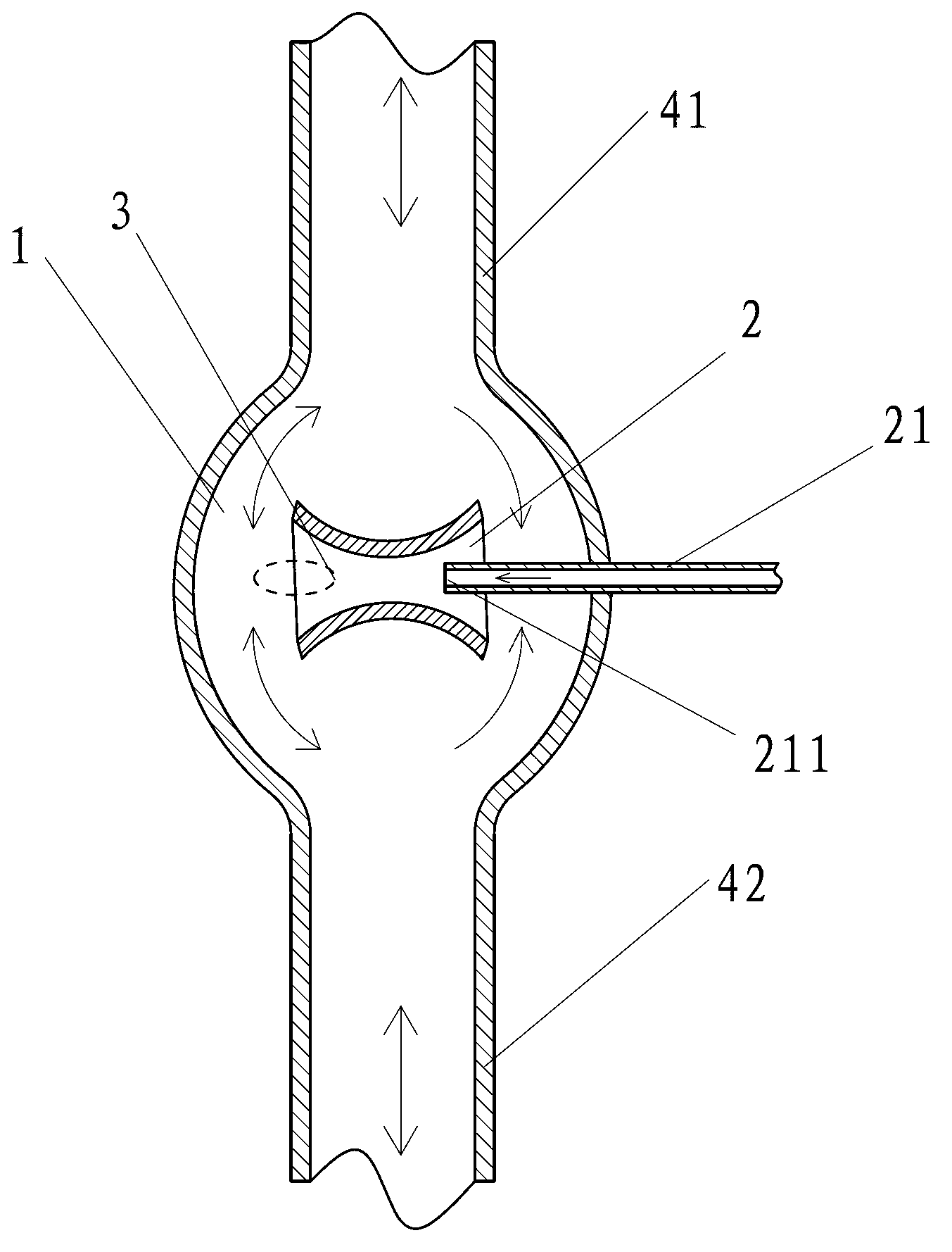
[0036] Such as figure 2 The difference between the working fluid internal combustion heater shown in Embodiment 1 is that the combustion chamber 3 is relocated at the fluid outlet of the jet pump 2 .

Embodiment 3

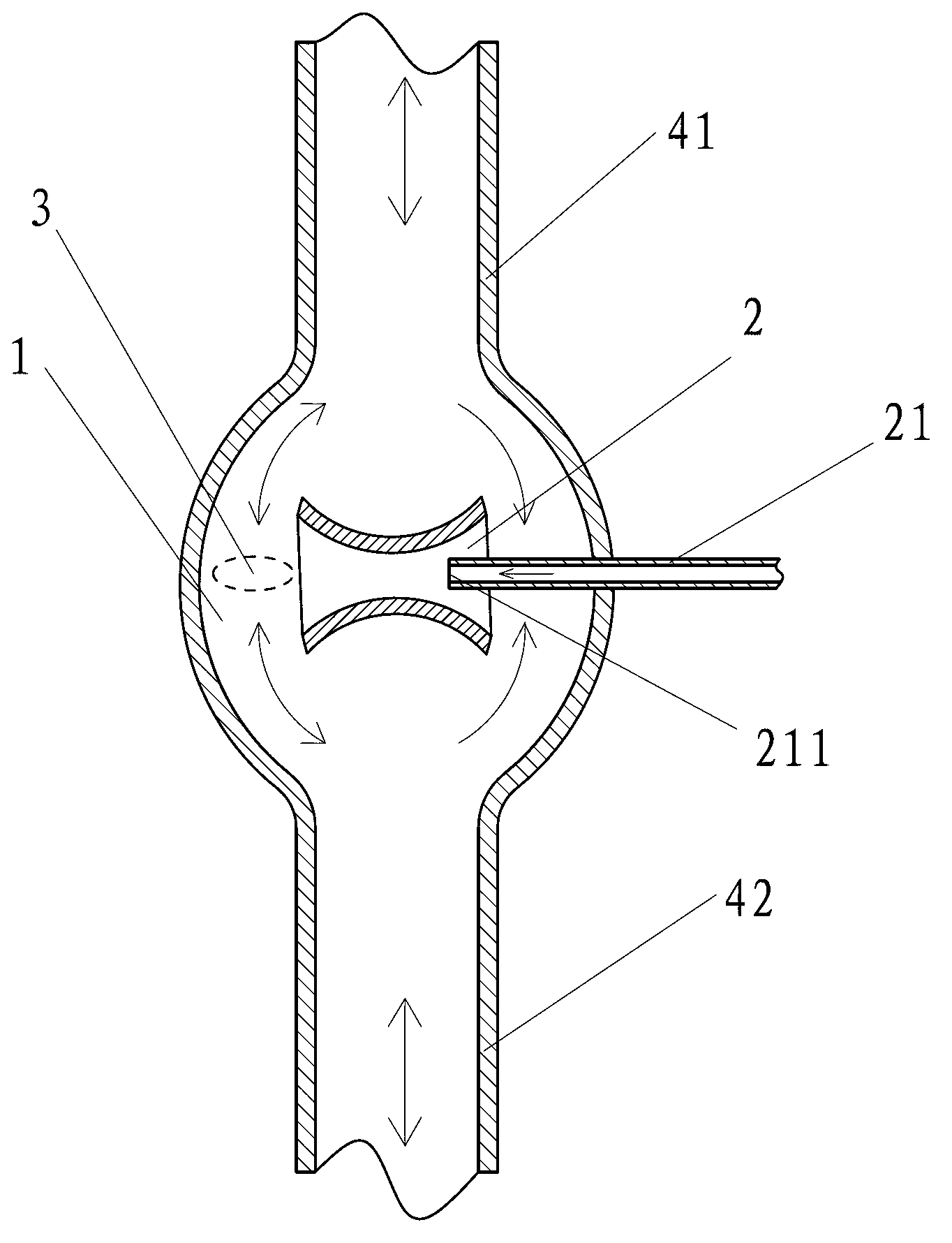
[0038] Such as image 3 The difference between the working fluid internal combustion heater shown in Embodiment 1 is that the combustion chamber 3 is relocated outside the fluid outlet of the jet pump 2 .


PUM


Abstract

The invention discloses a working medium internal combustion heater which comprises a working medium enveloping space, a jet pump and a combustion chamber, wherein the jet pump is arranged in the working medium enveloping space, and a high-pressure power fluid nozzle on the jet pump is communicated with an oxidizing agent source and / or a reducing agent source. The combustion chamber is arranged at a fluid outlet of the jet pump, or between the fluid outlet of the jet pump and the high-pressure power fluid nozzle of the jet pump, or outside the fluid outlet of the jet pump. By means of the working medium internal combustion heater, fluid jetted into the working medium enveloping space (for example, a space in a reciprocating passageway) is enabled to be mixed (a mixing process is contained and a chemical reaction happens) with fluid in the reciprocating passageway and to stay in a stable state, and therefore the fluid can work stably and react chemically and stably (combust fully in a mixed mode).

Description

technical field [0001] The invention relates to the field of thermal energy and power, in particular to a working fluid internal combustion heater. Background technique [0002] When it is necessary to fully mix a fluid with the reciprocating fluid in the working medium envelope, or fully mix and undergo a chemical reaction (such as fully mixed combustion), the fluid is usually injected directly into the working medium envelope, which This method will not only cause fluctuations in the injection state, but also cause displacement of the mixing zone (chemical reaction zone), which will affect stable operation. Therefore, need to invent a kind of can weaken the mixing region (comprising the region that mixes and takes place chemical reaction) between the fluid that injects into the working medium envelope and the fluid that reciprocates in the working medium envelope. ) of the affected device. Contents of the invention [0003] In order to solve the above problems, the tec...

Claims


Application Information

Patent Timeline
Patent Type & Authority Applications(China)
IPC IPC(8): F02G1/055
Inventor 靳北彪
Owner 山东沃达纸制品有限公司
Why Eureka
Try Eureka