Liquefied natural gas (LNG) engine energy recovery device and energy recovery method based on thermoelectric power generation technology

An energy recovery device, a technology of thermoelectric power generation, applied in generators/motors, engine components, combustion engines, etc., can solve the problems of ineffective use of energy, energy waste, low thermal efficiency, etc., to improve energy recovery efficiency and achieve thermal efficiency. Manage, improve fuel economy effects

Inactive Publication Date: 2013-06-26
HENAN AGRICULTURAL UNIVERSITY +1
View PDF7 Cites 5 Cited by
  • Summary
  • Abstract
  • Description
  • Claims
  • Application Information

AI Technical Summary

Problems solved by technology

Although the engine has experienced more than 100 years of development, its thermal efficiency is still low, as many as 60% of the energy in the fuel has not been effectively utilized, and the heat taken away by the engine exhaust alone accounts for 30% of the fuel combustion heat ~45%, the heat used for cooling accounts for about 30%, and most of this energy is lost to the air in the form of waste heat, resulting in huge energy waste and serious environmental pollution

Method used


Image

  • Liquefied natural gas (LNG) engine energy recovery device and energy recovery method based on thermoelectric power generation technology
  • Liquefied natural gas (LNG) engine energy recovery device and energy recovery method based on thermoelectric power generation technology
  • Liquefied natural gas (LNG) engine energy recovery device and energy recovery method based on thermoelectric power generation technology

Examples


Embodiment 1

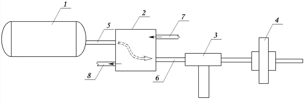
[0019] Embodiment 1: A kind of LNG engine energy recovery device based on thermoelectric power generation technology, see figure 1 , the device includes LNG tanks, thermoelectric generators, filters, regulators and mixers and other components. Wherein, the exhaust port of the LNG gas tank 1 is connected with the inlet of the cold end of the thermoelectric generator 2 through the LNG inlet pipe 5, and the outlet of the gasifier of the LNG engine is connected with the inlet of the hot end of the thermoelectric generator 2 through the coolant inlet pipe 7. 2 The outlet of the hot end is connected to the inlet of the LNG engine carburetor, and the outlet of the cold end of the thermoelectric generator 2 is connected with the filter 3, the voltage stabilizer 4, and the mixer in turn through the LNG outlet pipe as fuel for the LNG engine.

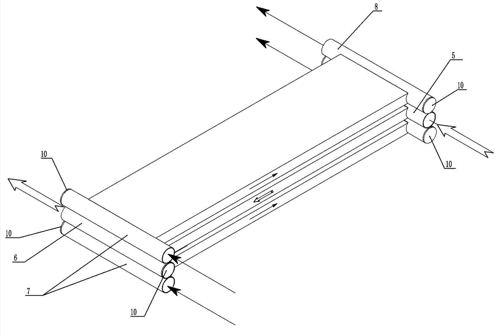
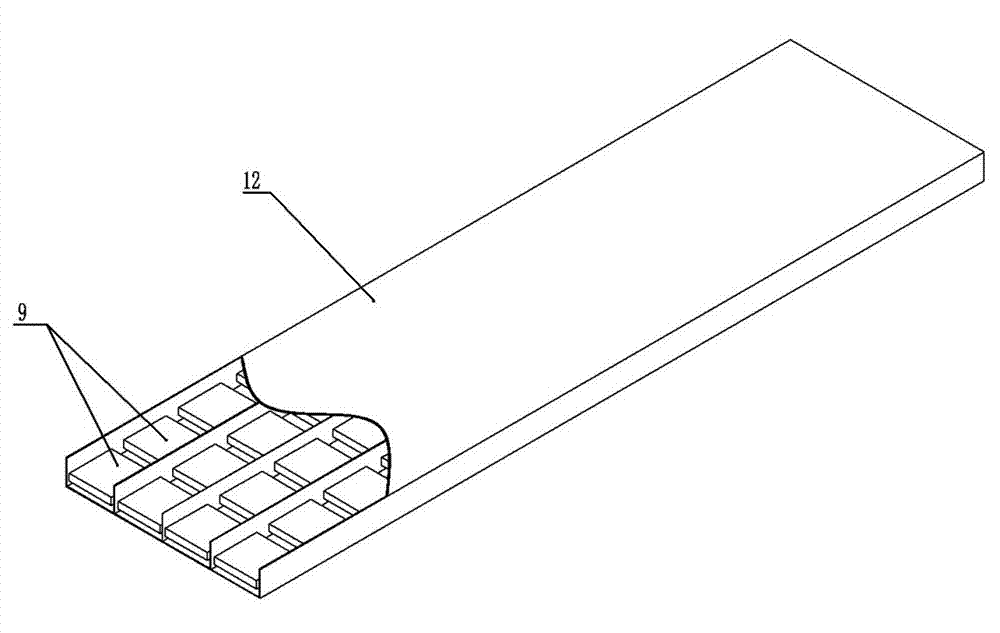
[0020] like Figure 2-Figure 4 As shown, the thermoelectric generator 2 includes three layers of porous flat tubes 12 superimposed on each oth...

Embodiment 2

[0021] Embodiment 2: The accompanying drawings are not drawn, and the content is basically the same as that of Embodiment 1, and the similarities will not be repeated. The difference is that the thermoelectric generator includes five layers of multi-layer porous flat tubes stacked on top of each other, and the upper layer of multi-hole flat tube coolant passages. One end is the coolant inlet pipe, and the other end is the coolant outlet pipe; the adjacent lower porous flat pipe is the LNG channel, one end of which is the LNG inlet pipe, and the other end is the LNG outlet pipe; the coolant channels and LNG channels are arranged alternately.

Embodiment 3

[0022] Embodiment 3: A method for recovering energy from an LNG engine based on thermoelectric power generation technology, using the gasification cooling capacity of the LNG gas tank as the cold end, using the engine cooling water as the hot end, and the cold end and the hot end are respectively located on both sides of the thermoelectric power generation sheet, The thermoelectric power generation technology is used to recover energy, and the gasified LNG is used as LNG engine fuel.


PUM


Abstract

The invention discloses a liquefied natural gas (LNG) engine energy recovery device and an energy recovery method based on the thermoelectric power generation technology. The LNG engine energy recovery device comprises a thermoelectric generator, wherein an air discharge outlet of an LNG tank is connected with the thermoelectric generator through an LNG air inlet pipe, and an LNG air outlet pipe of the thermoelectric generator is connected with a mixer after assign through a filter and a voltage stabilizer. According to the LNG engine energy recovery device and the energy recovery method based on the thermoelectric power generation technology, the LNG gasification function is achieved, energy recovery is achieved by using the thermoelectric power generation technology, waste heat energy of an engine is used, peculiar cold energy of an LNG vehicle is used, energy recover efficiency is improved to the maximum degree, fuel economy of the vehicle is improved, and heat management of the LNG engine can be achieved due to the fact that intake air temperature of the engine can be controlled by adjusting parameters such as flow of cooling liquid and load of the thermoelectric generator.

Description

technical field [0001] The invention relates to the technical field of thermoelectric power generation, in particular to an LNG engine energy recovery device and method based on thermoelectric power generation technology. Background technique [0002] With the rapid development of my country's motor vehicle population, automobiles not only bring us a lot of convenience, but also bring us huge challenges in terms of energy and environmental protection. By the end of 2011, the national motor vehicle population was 225 million, of which There are 106 million cars alone, among which the engine is still the main source of power. Although the engine has experienced more than 100 years of development, its thermal efficiency is still low, as many as 60% of the energy in the fuel has not been effectively utilized, and the heat taken away by the engine exhaust alone accounts for 30% of the fuel combustion heat ~45%, the heat used for cooling accounts for about 30%, and most of these e...

Claims


Application Information

Patent Timeline
Patent Type & Authority Applications(China)
IPC IPC(8): F02M21/02H02N11/00
CPCY02T10/12Y02T10/30
Inventor 马宗正余永昌李莉
Owner HENAN AGRICULTURAL UNIVERSITY
Why Eureka
Try Eureka