Lens and lamp using lens

A lens and lamp technology, applied in the field of lighting, can solve the problems of reduced brightness, small concentration ratio, unable to meet the spotlight lighting, etc., and achieve the effect of improving the utilization rate of light energy and small half-light intensity angle

Inactive Publication Date: 2013-06-26
OCEANS KING LIGHTING SCI&TECH CO LTD +1
View PDF4 Cites 11 Cited by
  • Summary
  • Abstract
  • Description
  • Claims
  • Application Information

AI Technical Summary

Problems solved by technology

However, the collimation effect of this simple form of optical collimation lens is not ideal, the half-light intensity angle is about 10 degrees, and the light-gathering ratio is small, which cannot meet the spotlight lighting in a small range
At the same time, the side of the light source cannot be used to emit light, resulting in low light energy utilization efficiency, which is about 60%, which greatly wastes light energy and reduces brightness.

Method used


Image

  • Lens and lamp using lens
  • Lens and lamp using lens
  • Lens and lamp using lens

Examples


Embodiment Construction

[0021] The specific implementation manners of the present invention will be described in detail below in conjunction with the accompanying drawings.

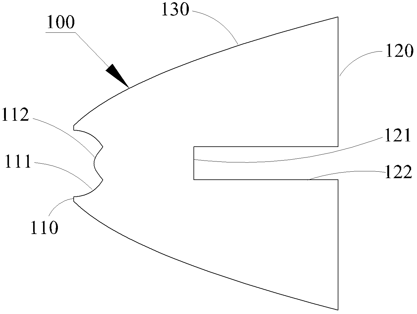
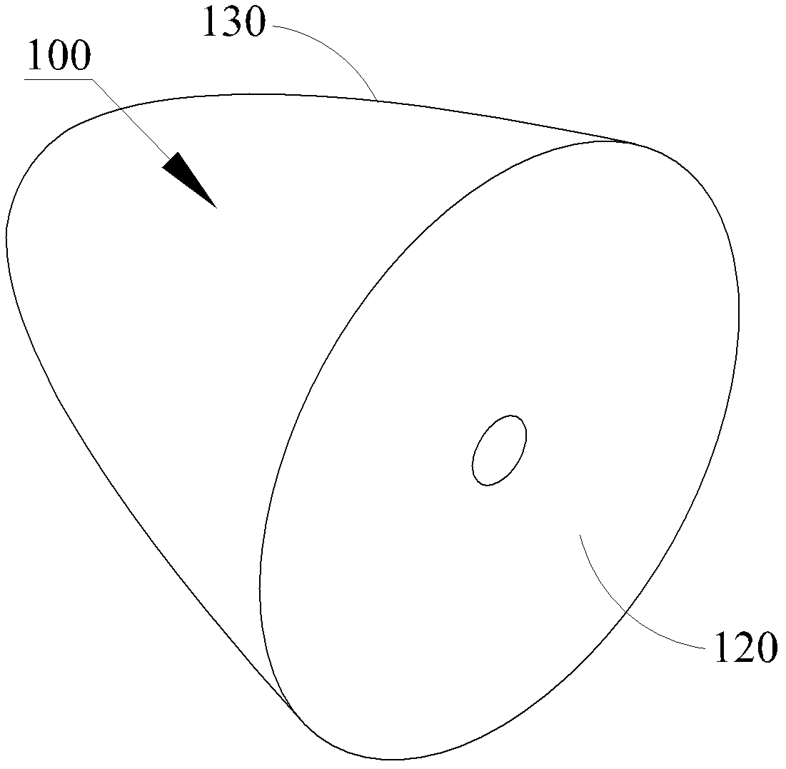
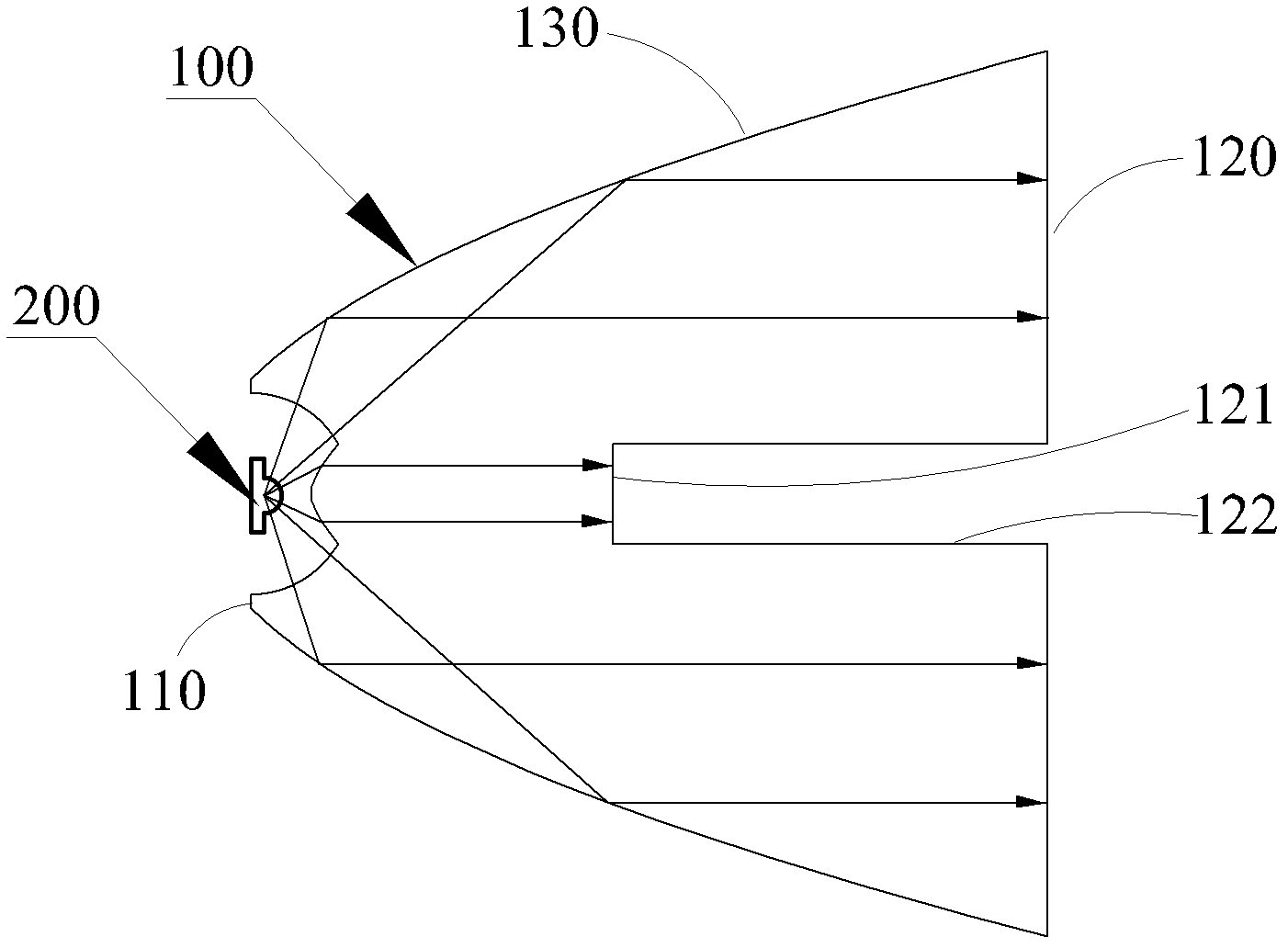
[0022] figure 1 is a structural sectional view of the lens in an embodiment, figure 2 Yes figure 1 Structural side view of the shown lens, image 3 Yes figure 1 Light path diagram for the lens shown. combine figure 1 and image 3 The lens 100 is a truncated cone lens symmetrical to the optical axis of the lens, including a first end face 110 with a smaller diameter, a second end face 120 with a larger diameter, and a side wall 130 connecting the first end face 110 and the second end face 120 . The middle part of the first end surface 110 is inwardly recessed to form a light source accommodating cavity for accommodating the light source 200 . The side surface 111 of the light source accommodating cavity is a spherical surface, and the bottom surface 112 of the light source accommodating cavity is a convex free-form surfac...


PUM


Abstract

The invention relates to a lens and a lamp using the lens. The lens is a round table type lens with a lens axis as a symmetric axis and comprises a first end face which is small in diameter, a second end face which is large in diameter and a side wall. The middle of the first end face concaves inwards to form a light source containing cavity suitable for containing a light source. The side face of the light source containing cavity is a spherical face. The bottom face of the light source containing cavity is an outwards-convex free curved face. The side wall is a parabolic face. A focal point of the parabolic face is overlapped with a spherical center of the spherical face. The light outlet diameter of the lens is 40 + / - 1% millimeters. The thickness of the lens is 40 + / - 1% millimeters. According to the lens and the lamp using the lens, due to collimation of the side wall and the free curved face, a half light intensity angle of the lens is enabled to be small, therefore, the lens is enabled to have a large condensation ratio, a light spot with a large condensation ratio is capable of being formed, and requirements of spotlighting in a small range are satisfied. Meanwhile, due to the fact that light of the side face of the light source is used, utilization rate of light energy is enabled to be largely improved.

Description

【Technical field】 [0001] The invention relates to the lighting field, in particular to a lens and a lamp using the lens. 【Background technique】 [0002] With the continuous improvement of the luminous efficiency of the light source, the application of LED in the field of lighting is also becoming wider and wider. However, in some special fields, such as medical treatment, public security and hunting fields, spotlight illumination in a small range is often required, so higher requirements are put forward for the secondary light distribution design of the optical collimator lens. [0003] At present, the traditional collimating and light distribution lenses are mostly spherical or aspheric in the form of concave and convex. However, the collimation effect of this simple form of optical collimation lens is not ideal, the half-light intensity angle is about 10 degrees, and the light-gathering ratio is small, which cannot meet the spotlight lighting in a small area. At the same...

Claims


Application Information

Patent Timeline
Patent Type & Authority Applications(China)
IPC IPC(8): F21V5/04F21V13/04F21Y101/02F21Y115/10
Inventor 周明杰杜金
Owner OCEANS KING LIGHTING SCI&TECH CO LTD
Why Eureka
Try Eureka