Al technical title is built by PatSnap Al team. It summarizes the technical point description of the patent document.
A technology of small hole measurement and measuring rod, which is applied in the field of measurement and inspection, can solve the problems that cannot meet the high precision, multi-parameter detection requirements, and difficulty in small hole measurement, and achieve the effect of simple structure, long service life and high measurement accuracy
Active Publication Date: 2013-06-26
FRIEDRICH MEASUREMENT INSTR CO LTD
View PDF7 Cites 9 Cited by
Summary
Abstract
Description
Claims
Application Information
AI Technical Summary
This helps you quickly interpret patents by identifying the three key elements:
Problems solved by technology
Method used
Benefits of technology
Problems solved by technology
[0002] In the existing technology, it is very difficult to realize multi-section and multi-direction measurement of small holes. The general measurement mechanism can only realize the measurement of a single direction of a cross-section, which cannot meet the requirements of high-precision and multi-parameter detection.
Method used
Image
Click on the blue label to locate the original text in one second.
Reading with bidirectional positioning of images and text.
Examples
Embodiment Construction
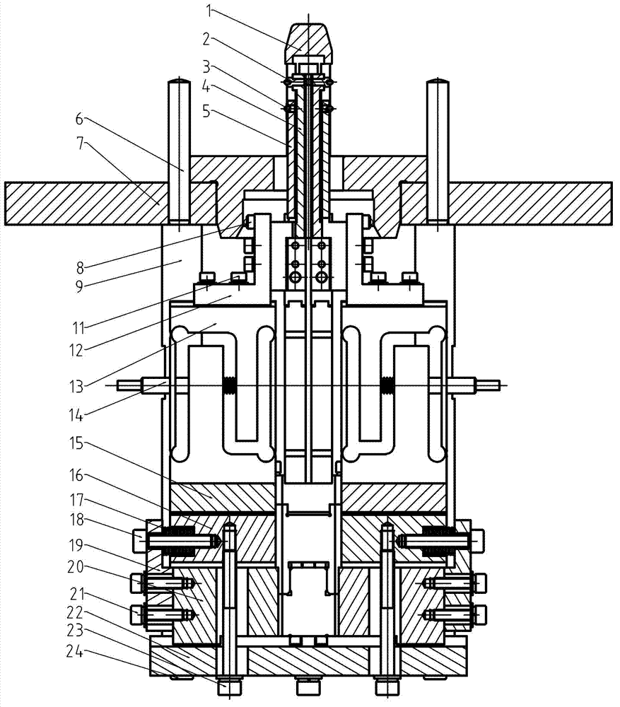
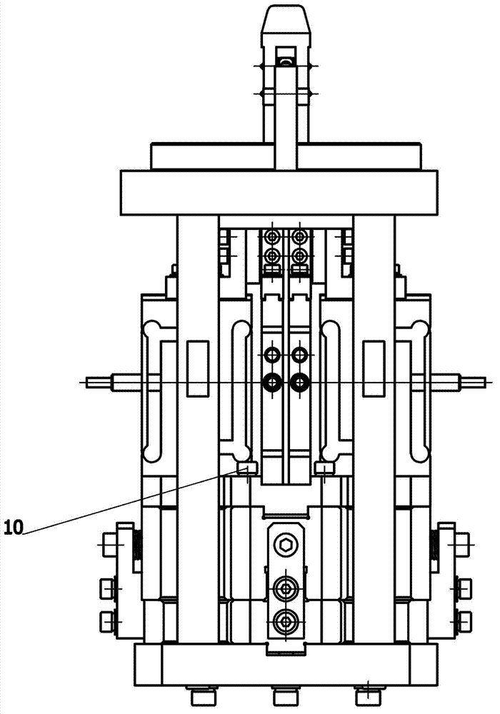
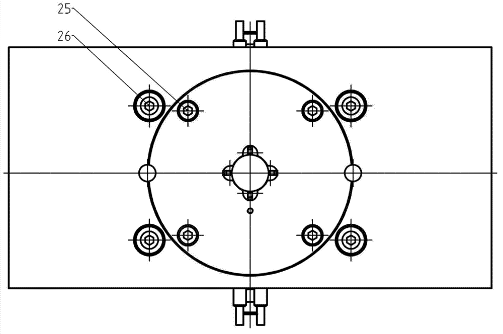
[0013] Below the present invention will be further described in conjunction with the embodiment in the accompanying drawing:
[0014] like Figure 1~3 As shown, the present invention mainly includes a positioning column 1, a first measuring head 2, a second measuring head 3, an inner measuring rod 4, an outer measuring rod 5, an upper mounting plate 7, a limit head 8, a connecting shaft 9, and a mounting block 12 , Flex gauge 13, sensor 14, fixed block 15, slide block 16, compression spring 17, adjustment screw 18, stop block 19, slide seat 20 and lower mounting plate 22.
[0015] The upper mounting plate 7 and the lower mounting plate 22 are connected by four connecting shafts 9 , and the upper ends of the connecting shafts 9 are fastened on the upper mounting plate 7 by seventh screws 26 . Four sliding seats 20 are evenly distributed on the lower mounting plate 22 , and the sliding seats 20 are fastened on the lower mounting plate 22 by fifth screws 24 . A slide block 16 i...
PUM
Abstract
The invention relates to a small hole measuring mechanism, and belongs to the technical field of measuring and detecting. Specifically, aperture variation is transmitted to a sensor through components such as a flexible gauge to detect inner diameter of a small hole. The small hole measuring mechanism comprises a positioning rod, a first measuring head, a second measuring head, an inner measuring rod, an outer measuring rod, an upper mounting plate, a limiting head, a connecting shaft, a mounting block, the flexible gauge, the sensor, a fixing block, a slide block, a pressure spring, a adjusting screw, a stopper, a slide seat and a lower mounting plate. The small hole measuring mechanism is simple, compact and reasonable in structure, wide in application range, capable of detecting various parameters simultaneously, high in measuring accuracy, long in measuring distance, convenient to adjust, high in repeatability, low in magnetic hysteresis, and long in service life during normal operation.
Description
technical field [0001] The invention relates to a small hole measuring mechanism. Specifically, the change amount of the hole diameter is transmitted to a sensor through components such as a flexure gauge, so as to realize the detection of the inner diameter of the small hole, and belongs to the technical field of measurement and inspection. Background technique [0002] In the prior art, it is very difficult to realize multi-section and multi-directional measurement of small holes. The general measurement mechanism can only realize the measurement of a single direction of a cross-section, which cannot meet the requirements of high-precision and multi-parameter detection. Contents of the invention [0003] The purpose of the present invention is to overcome the above disadvantages, thereby providing a small hole measuring mechanism, which can arrange two sections in the small hole at the same time, and arrange four measuring points on each section, so as to realize the meas...
Claims
Application Information
Patent Timeline
Application Date:The date an application was filed.
Publication Date:The date a patent or application was officially published.
First Publication Date:The earliest publication date of a patent with the same application number.
Issue Date:Publication date of the patent grant document.
PCT Entry Date:The Entry date of PCT National Phase.
Estimated Expiry Date:The statutory expiry date of a patent right according to the Patent Law, and it is the longest term of protection that the patent right can achieve without the termination of the patent right due to other reasons(Term extension factor has been taken into account ).
Invalid Date:Actual expiry date is based on effective date or publication date of legal transaction data of invalid patent.