
Test method for noise transmission path of rail vehicles

A technology of propagation path and test method, which is applied in the field of rail transit, can solve the difficulty of testing the near-field noise on the surface of the car body, increase the difficulty of identification, and cannot reflect the characteristics of the noise source of the rail vehicle. The effect of vibration reduction and noise reduction, etc. problem, achieve the effect of saving test time, fast switching, and ensuring consistency

Active Publication Date: 2015-08-19
武汉中车四方维保中心有限公司 +1
View PDF4 Cites 0 Cited by
  • Summary
  • Abstract
  • Description
  • Claims
  • Application Information

AI Technical Summary

Problems solved by technology

Although such a noise test method can objectively reflect the overall level of rail vehicle interior noise and vehicle radiated noise, it cannot reflect the characteristics of the noise source of the rail vehicle, the propagation characteristics of the noise to the interior of the vehicle, and the actual vibration reduction of the local structure of the vehicle. Noise effects, etc. are crucial for the design and manufacture of rail vehicles
[0003] Since the running speed of rail vehicles is very high, all above 200km / h, even reaching a speed of 350km / h or higher, the surface of the car body is very disturbed by the airflow, so the near-field noise of the car body surface and the wheel-rail noise test are compared. difficulty
In addition, due to the complex vehicle structure of rail vehicles, it is more difficult to identify the noise transmission path and the distribution characteristics of the sound field in the vehicle

Method used


Image

  • Test method for noise transmission path of rail vehicles
  • Test method for noise transmission path of rail vehicles
  • Test method for noise transmission path of rail vehicles

Examples


Embodiment 1

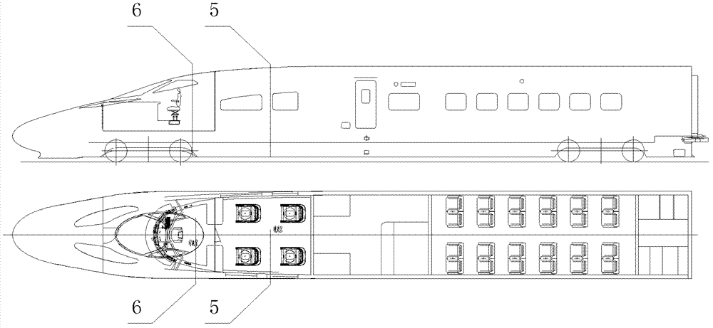
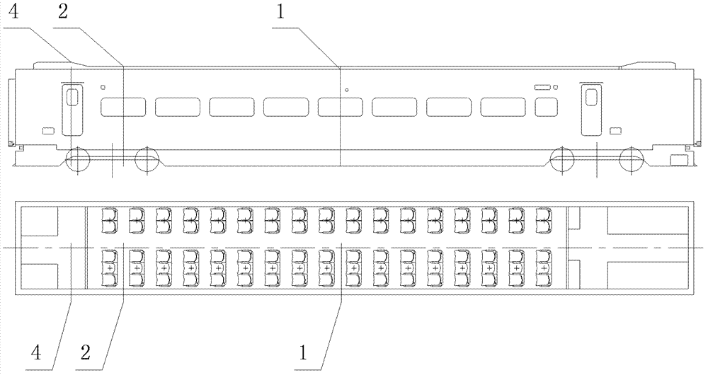
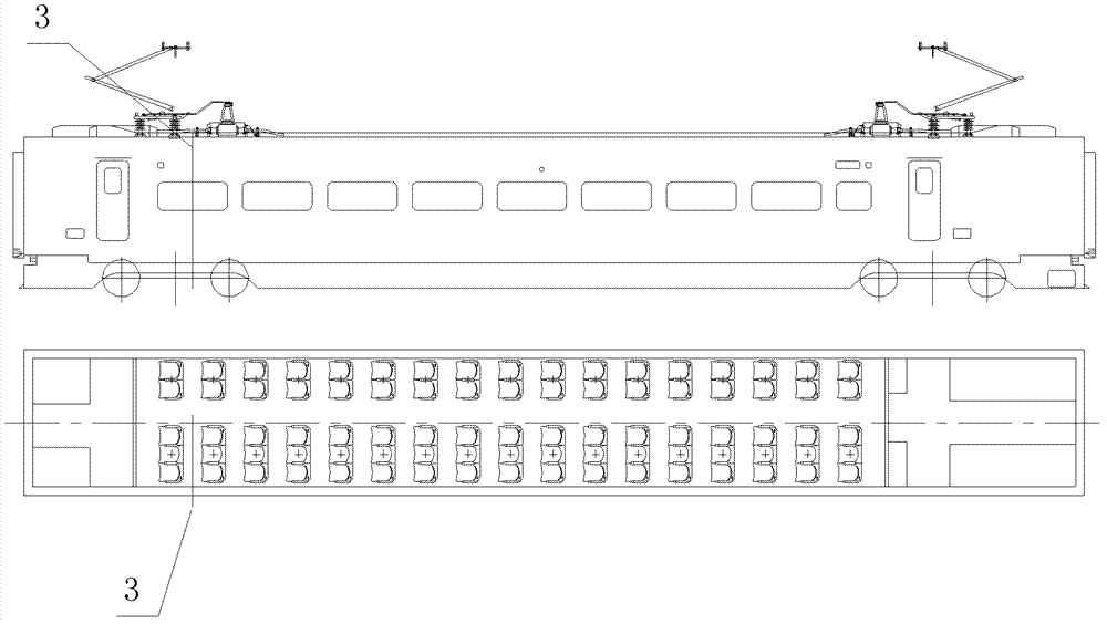
[0033] Example 1, such as Figure 1 to Figure 3 As shown, the rail vehicle noise propagation path test method specifically divides the middle section of the passenger compartment 1, the end section 2 of the passenger compartment, the pantograph area section 3, the passing platform section 4, and the sightseeing area according to the car body structure and functional divisions. Section 5 and cab section 6.

[0034] The above six test sections can basically reflect the distribution characteristics of rail vehicle noise. According to the plane layout of the vehicle, if there are special models such as a first-class car and a VIP car, and the structure of the vehicle has changed greatly, the test section can be added to the corresponding part of the car. If time permits, adding a test section between the middle section of the passenger compartment and the end section of the passenger compartment can further improve the accuracy of the analysis.

[0035] Such as Figure 4 As show...


PUM


Abstract

The invention discloses a noise transmission route testing method for a railway vehicle. The noise transmission route testing method is a brand-new engineering testing scheme, and by means of the method, the outside near-field noises of the railway vehicle in high-speed operation can be accurately tested, the transmission route of the noises of the railway vehicle and the distribution of in-vehicle sound field can be recognized, and testing basis with strong pertinence and practical applicability can be provided for the vibration and noise reduction design and manufacture of the railway vehicle. The noise transmission route testing method for the railway vehicle includes: arranging a plurality of mutually different sections according to the noise sources and the characteristics of a vehicle body, wherein each section is an independent two-dimensional sound field; choosing to test one or several items of noises outside the vehicle, vehicle body vibration, vibration of an inner decoration board, near-field noises in the vehicle and standard point noises in the vehicle on each section; and dividing each section of the vehicle body into a vehicle top, a lateral top, a lateral wall, a water blocking board and a floor when testing the standard point noises Lp in the vehicle.

Description

technical field [0001] The invention relates to a test method for noise sources and propagation paths applied to rail vehicles running on a line, and belongs to the technical field of rail transportation. Background technique [0002] At present, the noise test of rail vehicles is mainly for the purpose of vehicle acceptance. The standard point of 1200mm from the floor surface is tested in the seat area of ​​the vehicle, and the standard point of 1600mm from the floor surface is tested in the passing platform and aisle area; The standard point of m. Although such a noise test method can objectively reflect the overall level of rail vehicle interior noise and vehicle radiated noise, it cannot reflect the characteristics of the noise source of the rail vehicle, the propagation characteristics of the noise to the interior of the vehicle, and the actual vibration reduction of the local structure of the vehicle. Noise effects, etc. are crucial to the design and manufacture of ra...

Claims


Application Information

Patent Timeline
Patent Type & Authority Patents(China)
IPC IPC(8): G01M17/08
Inventor 郭建强梁建英林君山梁君海孙召进王东镇
Owner 武汉中车四方维保中心有限公司
Learn More