
Material tensile real constitutive curve testing technology

A curved and realistic technology, applied in the direction of applying stable tension/pressure to test the strength of materials, can solve the problems of high computational cost, many iterations, and significant impact of compression simulation, and achieve ideal results

Inactive Publication Date: 2013-06-26
SOUTHWEST JIAOTONG UNIV
View PDF5 Cites 28 Cited by
  • Summary
  • Abstract
  • Description
  • Claims
  • Application Information

AI Technical Summary

Problems solved by technology

Although the technical solution obtains the real tensile constitutive curve through finite element simulation and optical test curve, the following problems still exist in this solution: First, the technical solution simulates the shrinkage phenomenon during the tensile process of the sample by constructing the initial defect , but further studies have shown that the method of simulating the compaction of structural defects is only effective for some materials, that is, the initial defect size has a significant impact on the compaction simulation of some materials, so the method of structural defects cannot accurately simulate the compaction of all metal materials ; secondly, this technical solution uses the principle of dichotomy for finite element iterative calculation to obtain the real constitutive curve, which requires more iterations and relatively high calculation costs; thirdly, this technical solution uses an ordinary SLR camera for optical measurement, which can only Obtain the load-displacement curve and the external contour curve of the sample in the whole stretching process of the sample, but the deformation field of the sample cannot be obtained, so the reliability of the technical solution cannot be fully verified

Method used


Image

  • Material tensile real constitutive curve testing technology
  • Material tensile real constitutive curve testing technology
  • Material tensile real constitutive curve testing technology

Examples


Embodiment

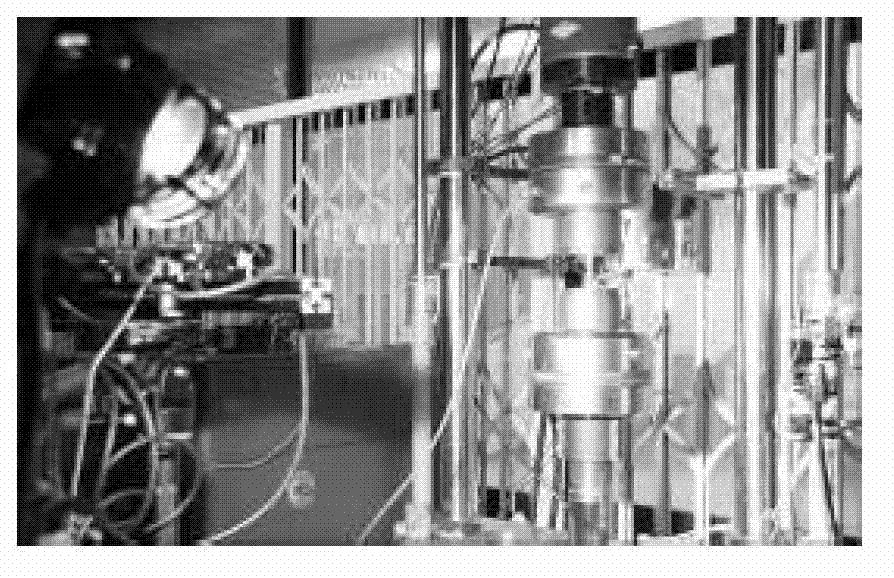
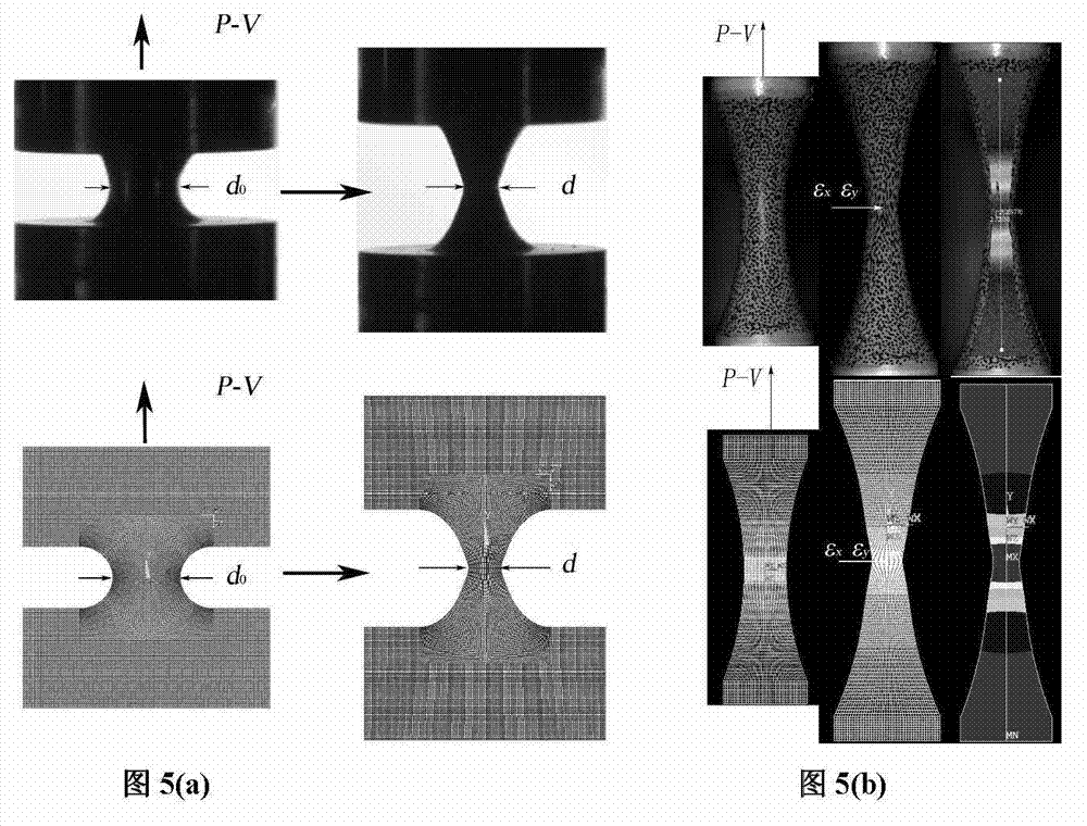
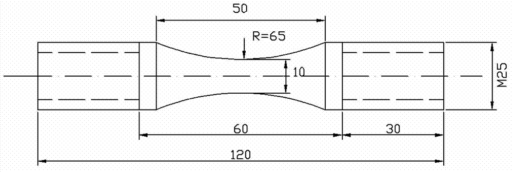
[0040] Taking 304 stainless steel as an example to further illustrate the specific implementation method of the technical solution of the present invention. Tensile test and VIC-3D optical measurement system such as Figure 4 As shown, the finite element simulation is carried out with ANSYS11.0. Figure 5 It is the comparison chart of funnel sample necking phenomenon test and finite element simulation, and the comparison chart of finite element simulation deformation field and optical measurement deformation field, Image 6 is the comparison result of the test load-displacement curve and the simulated load-displacement curve, Figure 7 is the optical measurement and simulation results of the minimum cross-sectional diameter d-displacement V curve at the necking root of the sample, Figure 8 is the photometry and simulation results of the shape curve of the funnel root at a certain loading moment of the sample, Figure 9 It is the result comparison of the real tensile consti...


PUM


Abstract

The invention discloses a material tensile real constitutive curve testing technology for obtaining an engineering stress-engineering strain curve and a load-displacement curve. The technology comprises the following steps of: obtaining a necking distortion profile curve and a stress strain field by non-contact optical measurement, establishing a finite element analytical model of a funnel round bar sample, stimulating the whole process that the sample is stretched until the necking is broken, and demarcating the real constitutive curve in an iteration solution mode. The technology disclosed by the invention overcomes the defects that the construction defect mode cannot precisely simulate a necking phenomenon of all metal material, the iteration times in the finite element iteration computation are more, and the computation cost is high; and the technology is combined with a non-contact optical distortion measurement system to monitor the tensile so as to obtain the load-displacement curve of the full-course sample tensile and the distortion field.

Description

technical field [0001] The invention belongs to the testing technology of material mechanical properties, especially the technical field of test data analysis and processing. Background technique [0002] Tensile test is a widely used method for testing the mechanical properties of materials. It can measure important basic mechanical properties parameters such as elastic modulus, strength, and plastic hardening of materials. It is the most basic reference for engineering component design and material selection. Usually, the load-displacement curve of the material can be obtained first from the tensile test, and then according to the original size of the sample (original cross-sectional area A 0 and the original gauge length L 0 ) to obtain the engineering stress-engineering strain curve (also called tensile constitutive curve). However, the real cross-sectional area A and gauge length L of the sample are constantly changing during the test, so the engineering stress-engine...

Claims


Application Information

Patent Timeline
Patent Type & Authority Applications(China)
IPC IPC(8): G01N3/08
Inventor 蔡力勋姚迪包陈
Owner SOUTHWEST JIAOTONG UNIV
Learn More