Infrared and low light image fusion method

A low-light image, infrared image technology, applied in image enhancement, image data processing, instruments, etc., can solve the problems of hindering real-time image fusion reconnaissance, no requirement for image fusion time, and reducing data volume, etc., to improve infrared/low-light Image fusion system, good engineering application value, and the effect of shortening time

Inactive Publication Date: 2013-06-26
NANJING UNIV OF SCI & TECH
View PDF3 Cites 24 Cited by
  • Summary
  • Abstract
  • Description
  • Claims
  • Application Information

AI Technical Summary

Problems solved by technology

On the battlefield, just having good image quality regardless of the computing speed of the system will bring a devastating blow to our side (such as: missile tracking system, fire control system). Similarly, increasing the computing speed of the system will reduce the Image quality will prevent us from obtaining comprehensive intelligence of the enemy (such as: reconnaissance system)
However, on the basis of existing algorithms and existing fusion system platforms, it is quite difficult to balance the two
[0004] Patent 1: Multi-strategy image fusion method under the framework of compressed sensing (CN102096913B, application date 2011.01.25) adopts the variable density sampling model of Fourier coefficient low-frequency full sampling, which reduces the amount of data that needs to be transmitted and reduces the complexity of fusion , which shortens the fusion time, but there is a problem of information loss
[0005] Patent 2: Image fusion method and equipment (CN101887581B, application date 2010.06.17) improves the traditional PCA (Principal Component Analysis) transformation image fusion method, and processes the source image into blocks so that the fused image can fully reflect the source image Their respective main information, but this method is mainly used in the field of medical images, and the processing process is not real-time
[0006] To sum up, these algorithms are mostly used in the fields of remote sensing and medicine at present, and there is no requirement for the fusion time of images, which cannot make the fusion of images meet real-time performance, thus hindering the real-time fusion and reconnaissance of images

Method used


Image

  • Infrared and low light image fusion method
  • Infrared and low light image fusion method
  • Infrared and low light image fusion method

Examples


Embodiment

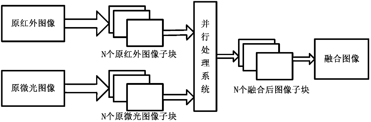
[0070] The present invention takes 4 high-speed DSPs (TMS320DM642) and FPGA (EPM7128AE) as the core, develops a real-time multi-spectral image fusion parallel processing system, and realizes image segmentation and accelerated fusion. The system uses 4 high-speed DSPs to work together, of which the main frequency of the DSP is as high as 720MHz, and the processing capacity can reach 5760MIPS. It will undertake image registration and block fusion of infrared and low-light images. FPGA realizes the recombination of N fusion sub-images. The video input is three PAL / NTSC standard video signals (choose two of them), the maximum input range is 0-1Vpp, the sampling accuracy is 8 bits, the sampling frequency is 27MHz for the full TV signal, and the brightness signal is 13.5MHz. The video output is one PAL / NTSC standard video signal, the maximum output range is 0-1.23Vpp, the gray resolution is 10 bits, and the video synthesis frequency is 27MHz. The image fusion system will organicall...


PUM


Abstract

The invention discloses an infrared and low light image fusion method. The method comprises the following steps of: (1) acquiring an original infrared image by using an infrared camera, and acquiring an original low light image by using a low light camera; (2) respectively partitioning the acquired original infrared image and the original low light image so as to divide the original infrared image and the original low light image into N mutually corresponding original image sub-blocks; (3) in a parallel processing system, simultaneously carrying out image fusion on the mutually corresponding original image sub-blocks in the original infrared image and the original low light image so as to obtain fused image sub-blocks; and (4) combining the fused image sub-blocks so as to generate a final fused image. The fused image obtained by the invention not only has a high image quality, but also has a high fusion speed, and therefore, the infrared and low light image fusion method has a wide application prospect in the military and civil fields of night vision surveillance, security monitoring, and the like.

Description

technical field [0001] The invention relates to the technical field of image fusion processing, in particular to an infrared and low-light image fusion method. Background technique [0002] Infrared / low-light image fusion technology has been widely used in the military field. It combines the advantages of rich scene details in low-light images and strong contrast between infrared image targets and backgrounds into one image, so that observers can get a better view of a certain scene. Accurate, comprehensive and reliable image information is highly valued. Since the 1990s, the military and scientific research institutions of various countries have conducted in-depth and meticulous research on infrared / low-light image fusion technology, and achieved fruitful results. During this period, a large number of practical and excellent algorithms have emerged, such as: arithmetic mean fusion algorithm, principal component analysis fusion algorithm, multi-resolution image fusion algor...

Claims


Application Information

Patent Timeline
Patent Type & Authority Applications(China)
IPC IPC(8): G06T5/50
Inventor 张俊举孙斌杨锋韩博杨文彬李宁陶媛媛陈云川王文治
Owner NANJING UNIV OF SCI & TECH
Why Eureka
Try Eureka