Ultra-thin dual-band microstrip patch antenna array rfid tag antenna

A technology of RFID tags and microstrip patch antennas, which is applied in the field of RFID tag antennas, can solve the problems of increased dimensions, inconsistencies, and rising costs of RFID tag antennas, achieve improved bandwidth range, obvious performance, and overcome miniaturization Effect

Active Publication Date: 2016-08-17
SHANGHAI YAOCHUAN INFORMATION TECH CO LTD
View PDF3 Cites 0 Cited by
  • Summary
  • Abstract
  • Description
  • Claims
  • Application Information

AI Technical Summary

Problems solved by technology

[0003] At present, the frequency bandwidth of RFID tag antennas used in various regions is still inconsistent in its high-frequency range. For example, Europe uses the frequency band of 866-868MHz, while the United States uses the frequency band of 902-928MHz. When switching in a wide area, the RFID tag antenna in the prior art is also difficult to be identified in areas with different frequency bandwidths due to bandwidth limitations
Moreover, because the existing RFID tag antenna has a significantly poor reading distance when the resonant frequency is lower than 910MHz
In order to achieve a good recognition effect, it is necessary to increase the thickness and length and width of the existing RFID tag antenna, which leads to an increase in the size and cost of the RFID tag antenna

Method used


Image

  • Ultra-thin dual-band microstrip patch antenna array rfid tag antenna
  • Ultra-thin dual-band microstrip patch antenna array rfid tag antenna
  • Ultra-thin dual-band microstrip patch antenna array rfid tag antenna

Examples


Embodiment Construction

[0018] The specific implementation process of the present invention will be described in detail below in conjunction with the accompanying drawings.

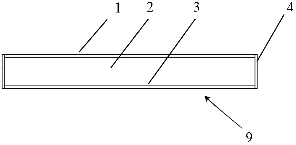
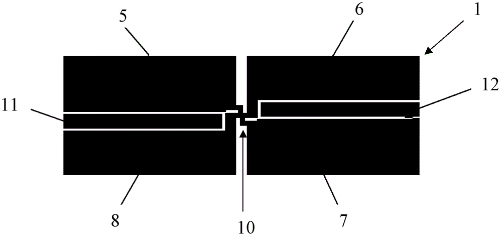
[0019] see figure 1 and figure 2 , the ultra-thin dual-frequency microstrip patch antenna array type RFID tag antenna 9 of the present invention has a substrate 2 and a substrate base plate 3 attached to the radiation element array 1 on the upper surface of the substrate 2 and the substrate base plate 3 on the lower surface and located at the radiation element The chip 10 in the center of the array has short-circuit surfaces 4 on both sides of the substrate 2 .

[0020] The radiating element array 1 of the present invention has 4 co-polarized asymmetric radiating elements forming an antenna array, and the 4 radiating elements are all linear poles in the same direction. The first radiation unit 5 and the fourth radiation unit 8 constituting the radiation unit array 1 are located on one side of the chip 10 , and the second radi...


PUM


Abstract

The invention relates to an ultra-thin dual-frequency microstrip patch antenna array RFID tag antenna. The RFID tag antenna has a unit array (1), a substrate (2) and a substrate bottom plate (3), and a radiation unit array (1 ) has an asymmetric structure around the chip, the first radiating unit (5) and the third radiating unit (7) form the low-frequency resonant system of the RFID tag antenna (9), and the second radiating unit (6) and The fourth radiating unit (8) constitutes a high-frequency resonance system of the RFID tag antenna (9). In this way, the dual-frequency effect is realized, so that the RFID tag antenna of the present invention achieves the compatibility of the performance of two different frequency bands in Europe and the United States, and realizes the dual-frequency band characteristic.

Description

technical field [0001] The invention relates to an RFID tag antenna, in particular to an ultra-thin dual-frequency microstrip patch antenna array type RFID tag antenna. Background technique [0002] RFID (Radio Frequency Identification)——radio frequency identification technology, is a non-contact automatic identification technology realized by radio frequency communication. It includes two main parts: electronic tag (tag) and reader (reader). The tag and the reader perform non-contact data transmission through the antenna to complete the automatic identification process at a certain distance. The current radio frequency identification system can be divided into low frequency system (30-300KHz), medium-high frequency system (3-30MHz) and ultra-high frequency and microwave system (300MHz-3GHz or greater than 33GHz) according to the frequency band used. As a high-tech and information standardization basis for fast, real-time and accurate collection and processing of informatio...

Claims


Application Information

Patent Timeline
Patent Type & Authority Patents(China)
IPC IPC(8): H01Q1/38H01Q21/30
CPCH01Q1/2225H01Q21/065H01Q21/30G06K19/07754G06K19/07786
Inventor 刘智佳杜国宏
Owner SHANGHAI YAOCHUAN INFORMATION TECH CO LTD
Why Eureka
Try Eureka