
Radio frequency direct acquisition broadband digital receiver system and method and radio observation system

A digital receiver and radio frequency direct sampling technology, applied in transmission systems, electrical components, etc., can solve the problems of multiple external noises, unavoidable parallel sampling non-uniform errors, interference system processing, etc., to achieve increased bandwidth and simple expansion methods Effective, widening the bandwidth range

Inactive Publication Date: 2020-08-18
SHANDONG UNIV
View PDF6 Cites 8 Cited by
  • Summary
  • Abstract
  • Description
  • Claims
  • Application Information

AI Technical Summary

Problems solved by technology

The single-bit sampling digital receiver has loss in amplitude and phase, and the two-tone dynamic of the system is low
The digital receiver that uses multiple ADCs to sample in parallel and time alternately greatly increases the sampling rate, but the analog bandwidth of the ADC device becomes its limiting factor. At the same time, due to the difference in response between parallel channels and the difference in sampling clocks between channels, Unavoidable non-uniform errors leading to parallel sampling
[0004] In short, in view of the high-frequency radio astronomy observations' requirements for receiver system sampling and large bandwidth, the current receiver has problems such as large and complex systems, limited signal requirements, and serious signal distortion.
Moreover, due to the weak electromagnetic wave energy of solar radiation, when dealing with high-frequency solar radio signals, traditional solar radio observation receivers often use the signal down-frequency processing and then input it into the digital receiver. Multiple external noises interfere with the system's processing of solar radio signals

Method used


Image

  • Radio frequency direct acquisition broadband digital receiver system and method and radio observation system
  • Radio frequency direct acquisition broadband digital receiver system and method and radio observation system

Examples


Embodiment 1

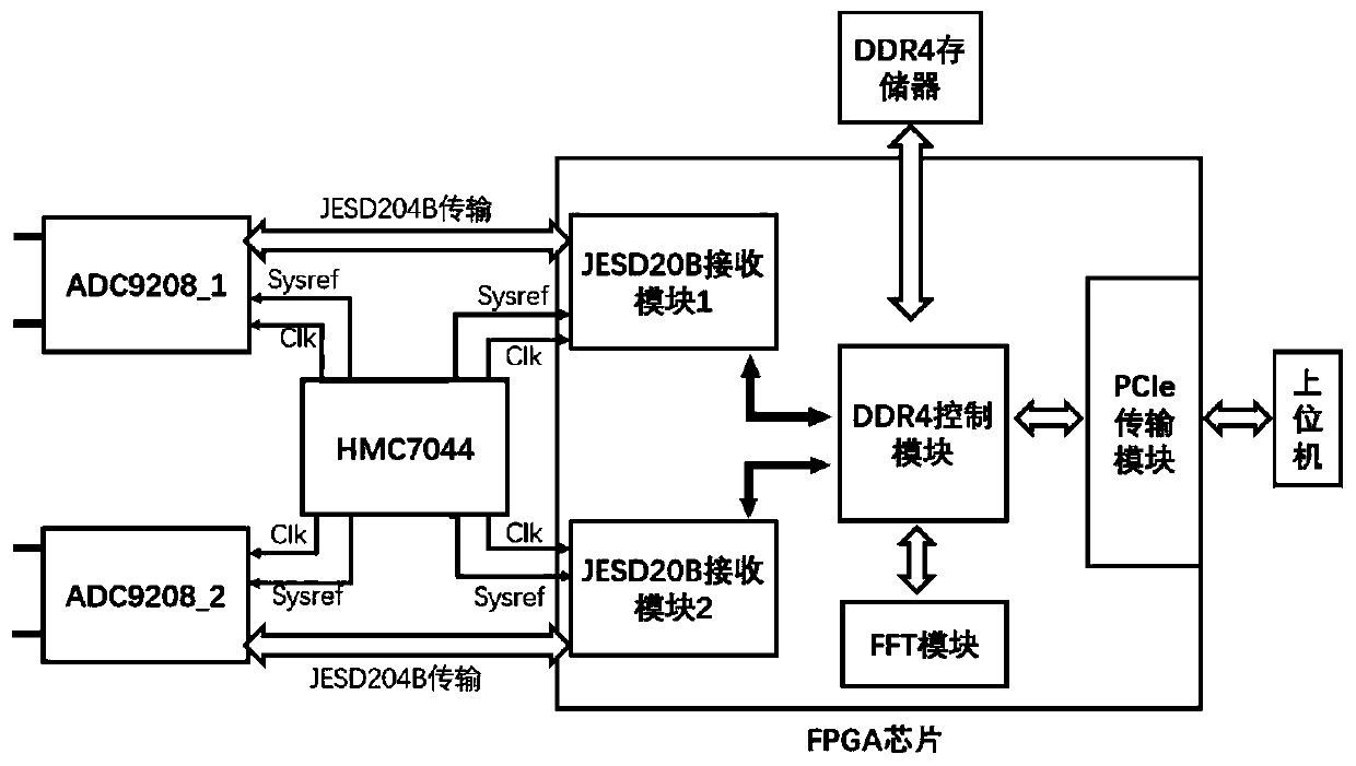
[0023] In the technical solutions disclosed in one or more embodiments, such as figure 1 Shown, a kind of radio frequency directly collects wideband digital receiver system, comprises FPGA processing unit, clock module and at least two ADC conversion modules, and described FPGA processing unit is connected with each ADC conversion module, and clock module is respectively connected with ADC conversion module and The FPGA processing unit is connected to provide a device clock and a synchronous clock; the FPGA processing unit is configured to set the signal bandwidth range of each input channel of the ADC conversion module, so that the signal bandwidth range of all channels is greater than that of each channel after being superimposed signal bandwidth range.

[0024] The signal bandwidth ranges of all channels are superimposed to be greater than the signal bandwidth ranges of each channel, and at least a part of the signal bandwidth ranges of each channel does not overlap, and ma...

Embodiment 2

[0055] The present embodiment provides a kind of control method of radio frequency direct acquisition wideband digital receiver system, and this method can be realized in FPGA processing unit, comprises the following steps:

[0056] Step 1. Configure the clock module and the ADC conversion module, and set the signal bandwidth range of each channel of each ADC conversion module, so that the signal bandwidth range of all channels is greater than the signal bandwidth range of each channel after being superimposed;

[0057] Step 2, receiving the data transmitted by each ADC conversion module;

[0058] Step 3, deframing the received data to obtain AD data;

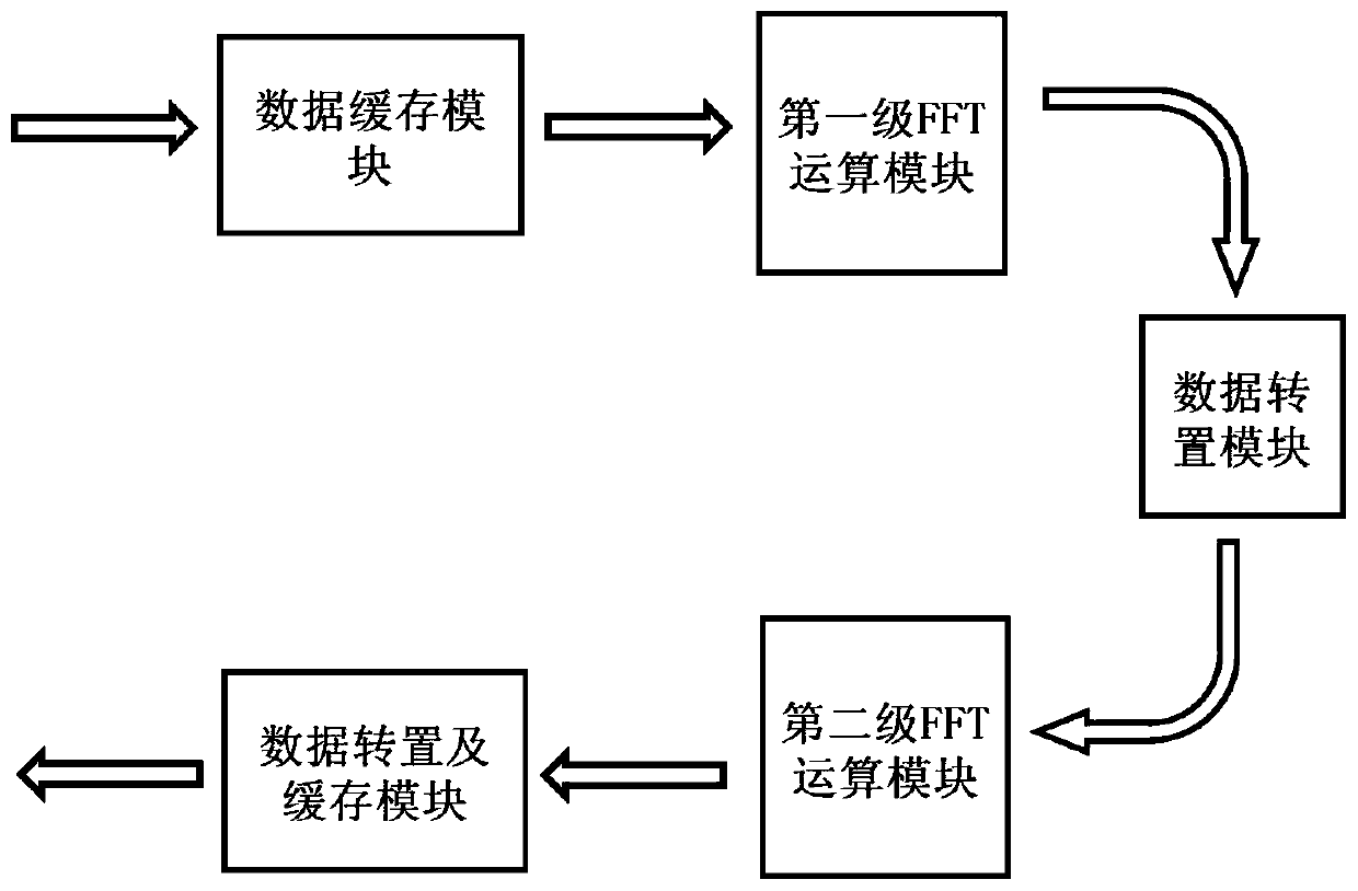
[0059] Step 4: Perform fast Fourier transform using a mixed-radix FFT algorithm to process the obtained AD data to obtain transformed data.

[0060] In this embodiment, the input channels of the ADC conversion module for direct signal acquisition are set to different signal bandwidth ranges, and the signal bandwidth range of t...

Embodiment 3

[0085] This embodiment provides a radio astronomy observation system, including an antenna, a radio frequency front-end module and a digital receiver connected in sequence, and the digital receiver adopts the radio frequency direct acquisition broadband digital receiver system described in Embodiment 1, and the The radio frequency front-end module includes a plurality of filters, and the filters are connected one-to-one to the input signal channels of the ADC conversion module, and the output signal bandwidth range of the filters corresponds to the signal broadband range of the input signal channels of the connected ADC conversion module.

[0086] The corresponding signal broadband range means that the signal broadband range is consistent. If the signal broadband range of the input signal channel of the ADC conversion module is 0 to 1.5 GHz, the corresponding filter output signal bandwidth range is also 0 to 1.5 GHz.

[0087] It can be understood that the radio frequency front-...


PUM


Abstract

The invention provides a radio frequency direct acquisition broadband digital receiver system and method and a radio observation system. The receiver system comprises an FPGA processing unit, a clockmodule and at least two ADC conversion modules,. The FPGA processing unit is connected with each ADC conversion module, and the clock module is connected with the ADC conversion modules and the FPGA processing unit. The FPGA processing unit is configured to be used for setting the signal bandwidth range of each input channel of the ADC conversion module, so that the signal bandwidth ranges of allthe channels are larger than the signal bandwidth range of each channel after being superposed. Signal acquisition is carried out in a radio frequency direct acquisition mode. The same clock module isarranged between the FPGA processing unit and the ADC conversion module. Expansion of the ADC conversion modules and signal superposition of input channels of the ADC conversion modules can be realized, the number of the ADC conversion modules is expanded according to the required signal bandwidth range, the bandwidth range of receivable signals of the digital receiver is directly improved, and the expansion mode is simple and effective.

Description

technical field [0001] The present disclosure relates to the related technical field of radio astronomy observation equipment, and specifically relates to a radio frequency direct acquisition broadband digital receiver system, method and radio observation system, which can be used for solar radio observation. Background technique [0002] The statements in this section merely provide background information related to the present disclosure and may not necessarily constitute prior art. [0003] At present, receiver systems for high-frequency radio astronomy observations include: analog superheterodyne down-conversion combined with low-IF sampling digital receivers, channelized digital receivers, compressed sampling digital receivers, and single-bit sampling digital receivers. receivers and alternate sampling digital receivers, etc. The inventors found that although these receivers expand the bandwidth of the acquisition system, they all have certain problems. Analog superhe...

Claims


Application Information

Patent Timeline
IPC IPC(8): H04B1/16
CPCH04B1/16
Inventor 严发宝张园园张磊尚自乾陈耀武昭苏艳蕊路光王冰
Owner SHANDONG UNIV
Learn More