Anomaly diagnostic device and industrial machine

A diagnostic device and abnormal diagnosis technology, applied in the direction of registering/instructing the work of machines, instruments, electrical testing/monitoring, etc., can solve problems such as the impact of maintenance work efficiency on diagnostic processing performance, difficulty in setting diagnostic processing benchmark values, etc., to reduce Effects of communication capacity, improved diagnostic accuracy, and reduced communication data volume

Active Publication Date: 2013-06-26
HITACHI LTD
View PDF8 Cites 16 Cited by
  • Summary
  • Abstract
  • Description
  • Claims
  • Application Information

AI Technical Summary

Problems solved by technology

However, maintenance work efficiency is affected by the performance of diagnostic processing based on measurement data, and it is particularly difficult to set a reference value for the above diagnostic processing

Method used


Image

  • Anomaly diagnostic device and industrial machine
  • Anomaly diagnostic device and industrial machine
  • Anomaly diagnostic device and industrial machine

Examples


no. 1 Embodiment approach

[0040] refer to Figure 1 to Figure 5 The first embodiment of the present invention will be described.

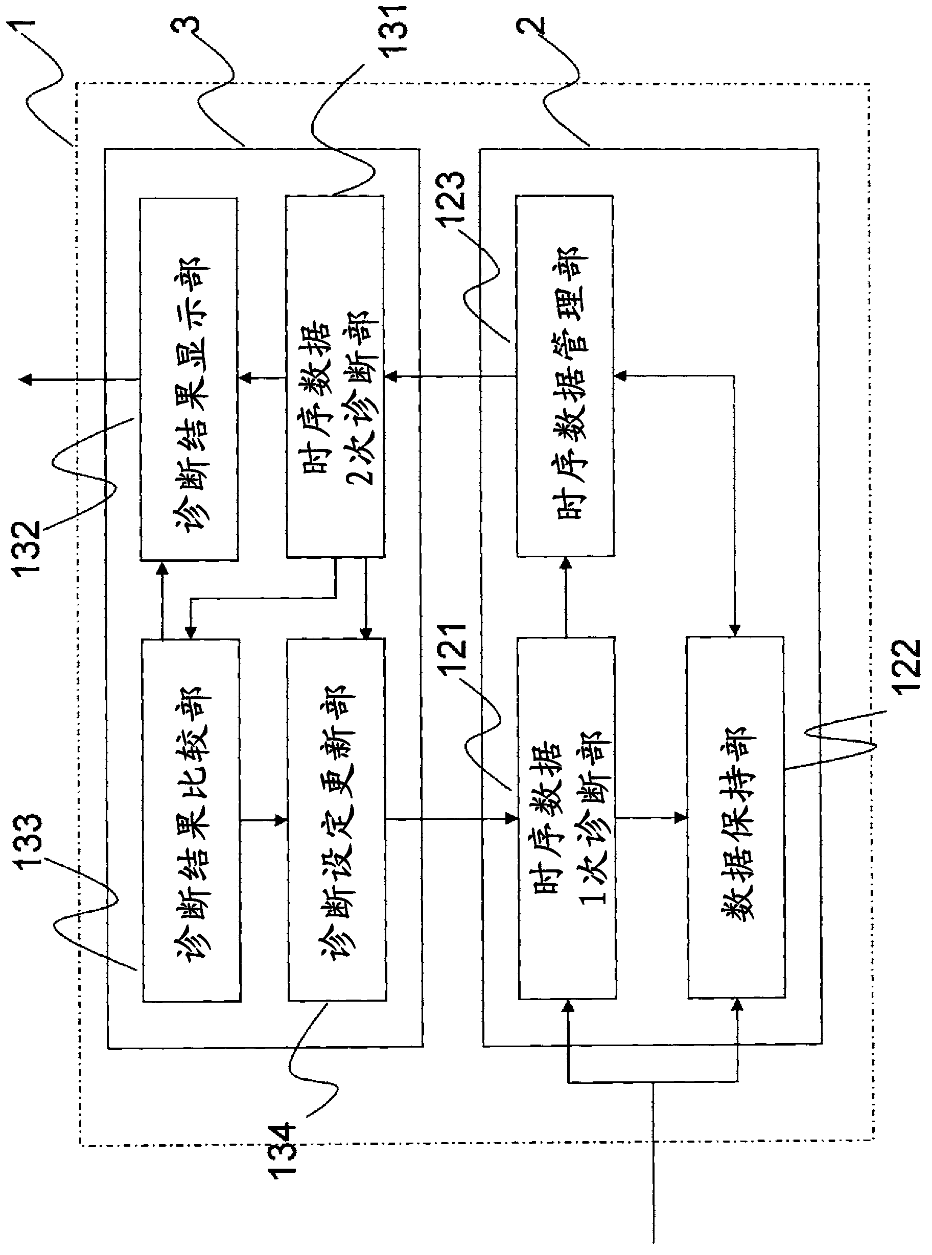
[0041] figure 1It is a figure which shows the structure of the abnormality diagnosis apparatus of this invention. The abnormality diagnosis device 1 is composed of a machine side diagnosis device 2 (first diagnosis device) installed in a machine side computer and a server side diagnosis device 3 (second diagnosis device) installed in a server. The machine-side diagnosis device 2 is composed of a time-series data primary diagnosis unit 121 (first time-series data diagnosis unit), a data storage unit 122 , and a time-series data management unit 123 . The server-side diagnosis device 3 is composed of a time-series data secondary diagnosis unit 131 (second time-series data diagnosis unit), a diagnosis result display unit 132 , a diagnosis result comparison unit 133 , and a diagnosis setting update unit 134 .

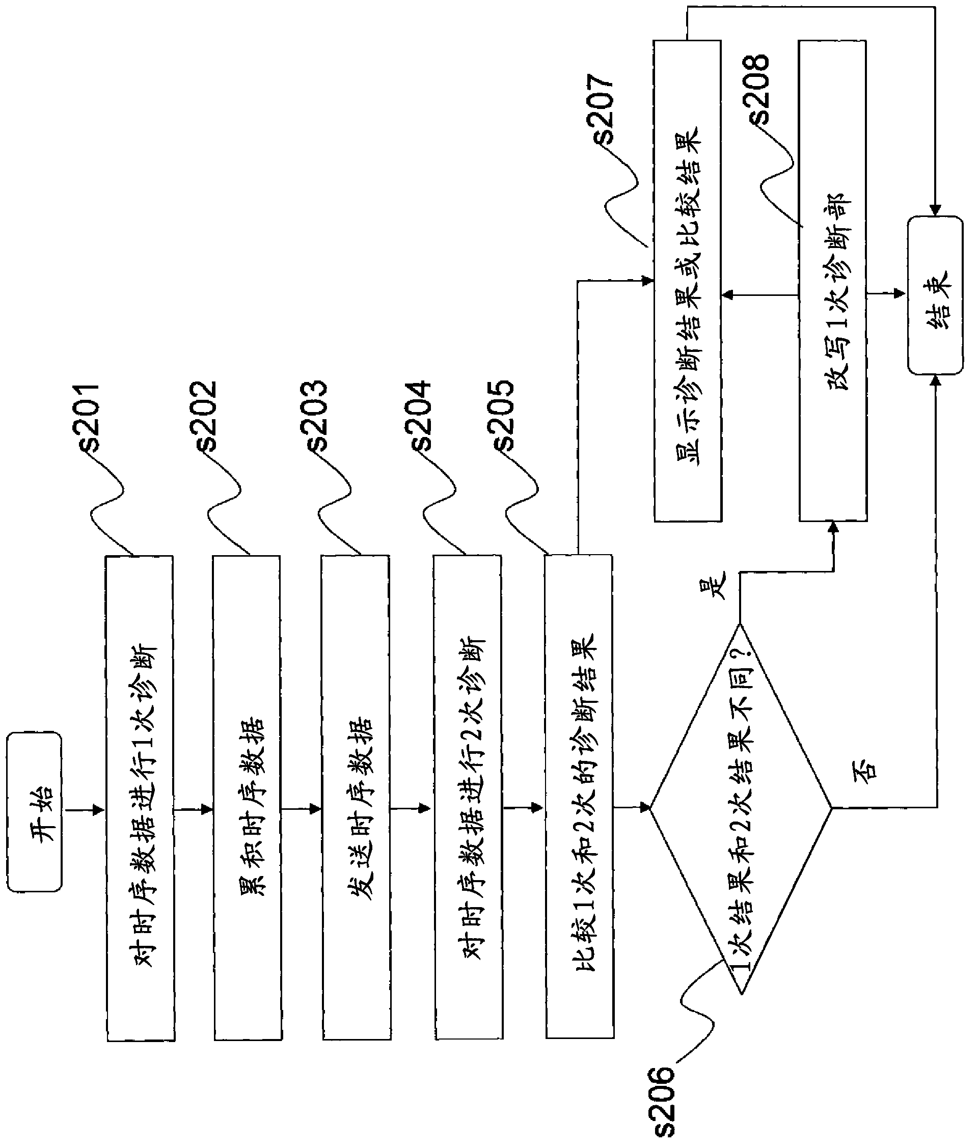
[0042] figure 2 It is a flowchart showing the functions and ope...

no. 2 Embodiment approach

[0062] use Figure 7 and the previous figure 1 , figure 2 as well as Figure 4 A second embodiment of the present invention will be described. figure 1 as well as figure 2 The configuration, functions, and operations of the abnormality diagnosis device 1 according to the present invention shown are the same as those described in the first embodiment, and thus are omitted.

[0063] Details of the functions and operations of this embodiment will be described below. Figure 7 It is the data obtained by digitizing the signal obtained by the abnormality diagnosis device 1 from a sensor mounted on a device (not shown) as the diagnostic target, that is, the time-series data 401 of the pressure sensor value and the signal indicating the activation state of the device 402 diagram of the timing data. It shows that the start and stop are repeated over time, and the pressure sensor value also fluctuates with the start and stop. In this embodiment, an abnormality occurs in the equ...

no. 3 Embodiment approach

[0071] Next, use Figure 8 An application example of the abnormality diagnosis device of the present invention will be described. Figure 8 It is a figure which shows the whole structure of the large hydraulic excavator which is an example of the industrial machine to which the abnormality diagnosis apparatus of this invention is applied, and an abnormality diagnosis apparatus.

[0072] The large-scale hydraulic shovel 8 can perform actions such as excavation through various operating mechanisms provided. Bucket 801 , arm 802 , and boom 803 constitute a work machine, and these are driven by hydraulic cylinders 811 , 812 , and 813 . In addition, the hydraulic shovel 8 includes a revolving body 806 , a revolving mechanism 804 for rotating the revolving body 806 , and left and right crawler devices 805 (only one side shown in the figure) as traveling mechanisms of the hydraulic shovel as a whole. The swivel mechanism 804 includes a hydraulic motor (not shown) for swiveling, and...


PUM


Abstract

Provided is an anomaly diagnostic device, as well as an industrial machine provided with the anomaly diagnostic device, which, when performing state diagnostics of a machine or an apparatus on the basis of time-series data generated by a sensor, can improve the accuracy of diagnosis even if the computer disposed upon the machine side does not have sufficient processing capability, and for which the amount of communication data is decreased so as to reduce the volume of communication. A machine-side diagnostic device (2) diagnoses time-series data generated by the sensor to acquire a primary diagnostic result and extracts the time-series data relating to the primary diagnostic result so as to output thereof together with the primary diagnostic result to a server-side diagnostic device (3), whereupon the server-side diagnostic device (3) diagnoses the time-series data to acquire a secondary diagnostic result and displays the secondary diagnostic result together with the primary diagnostic result. In addition, the diagnostic results are compared, and if the comparison results are different, the diagnostic processing of the machine-side diagnostic device (2) is updated.

Description

technical field [0001] The present invention relates to an abnormality diagnosis device installed in a machine or equipment to diagnose the state of the machine or equipment, and an industrial machine equipped with the abnormality diagnosis device. Background technique [0002] Among industrial machines, there are industrial machines that are required to operate continuously 365 days a day, 24 hours a day, almost without stopping. Examples of such industrial machines include working machines such as large-scale hydraulic shovels or mechanical equipment operated in mines or the like. This kind of industrial machinery (hereinafter referred to as machinery as appropriate) has a large impact when it stops due to failure, etc. Therefore, in order not to stop due to failure, measures are taken to make the machine or a part of the machine (component part) through maintenance. Various equipment to achieve the best condition and other measures. [0003] General maintenance is perio...

Claims


Application Information

Patent Timeline
Patent Type & Authority Applications(China)
IPC IPC(8): G05B23/02
CPCG05B23/0208G05B23/0221G05B23/0237G05B23/0264G05B23/0272G07C3/00G06F11/30
Inventor 铃木英明中村浩三汤田晋也内山宏树
Owner HITACHI LTD
Why Eureka
Try Eureka