
Pressure trigger control method for breathing machine

A technology of trigger control and ventilator, applied in the direction of ventilator, etc., can solve the problem of false triggering of patients and difficult triggering of patients, and achieve the effect of easy triggering

Inactive Publication Date: 2013-07-03
BEIJING AEONMED
View PDF0 Cites 9 Cited by
  • Summary
  • Abstract
  • Description
  • Claims
  • Application Information

AI Technical Summary

Problems solved by technology

For the ventilator trigger control method, it is very important to adjust the trigger level reasonably. The trigger level can be adjusted artificially to make it close to zero, which can shorten the trigger time and improve synchronization, but some patients are prone to false triggers.
In addition, when there is PEEPI in the patient's respiratory system, the trigger pressure value is calculated according to the conventional pressure sensitivity, and it is difficult for the patient to trigger

Method used


Image

  • Pressure trigger control method for breathing machine
  • Pressure trigger control method for breathing machine

Examples


no. 1 example

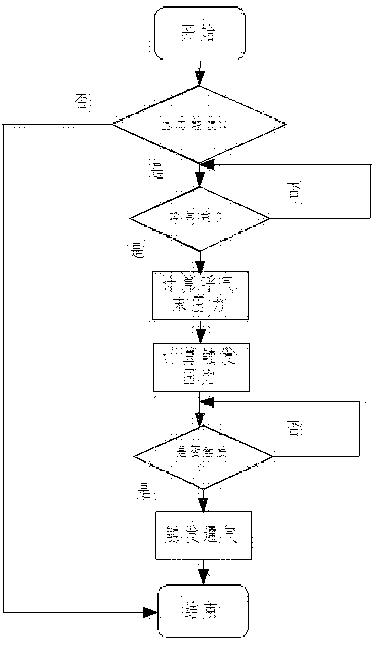
[0039] see figure 2 , the first embodiment of the method of ventilator pressure trigger control of the present invention includes the following steps:

[0040] (1) Detect the trigger mode, if it is the pressure trigger mode, then perform step (2), otherwise the program ends;

[0041] (2) Detect the end state of the breathing cycle, if the forced expiratory time ends, execute step (3), otherwise, continue to execute step (2);

[0042] (3) Calculate the end-expiratory pressure, and calculate the average value according to the pressure value measured in the same breathing cycle when the pressure remains unchanged to obtain the end-expiratory pressure, and then perform step (4);

[0043] (4) Calculate the trigger pressure, obtain the sum of the end-expiratory pressure and the preset pressure trigger sensitivity, then make a difference between the detected airway pressure and the obtained sum, and then perform step (5);

[0044] (5) Judge the trigger state of the ventilator, whe...

no. 2 example

[0046] see figure 2 , the second embodiment of the method for triggering control of ventilator pressure according to the present invention specifically includes the following steps:

[0047] (1) Detect the trigger mode, if it is the pressure trigger mode, then perform step (2), otherwise the program ends;

[0048] (2) Detect the end state of the breathing cycle, if the forced expiratory time ends, execute step (3), otherwise, continue to execute step (2);

[0049] (3) Calculate the end-expiratory pressure, the end-expiratory pressure value can be obtained through real-time monitoring of special equipment, and then perform step (4);

[0050] (4) Calculate the trigger pressure, obtain the sum of the end-expiratory pressure and the preset pressure trigger sensitivity, then make a difference between the detected airway pressure and the obtained sum, and then perform step (5);

[0051] (5) Judge the trigger state of the ventilator, when the airway pressure is less than the final...


PUM


Abstract

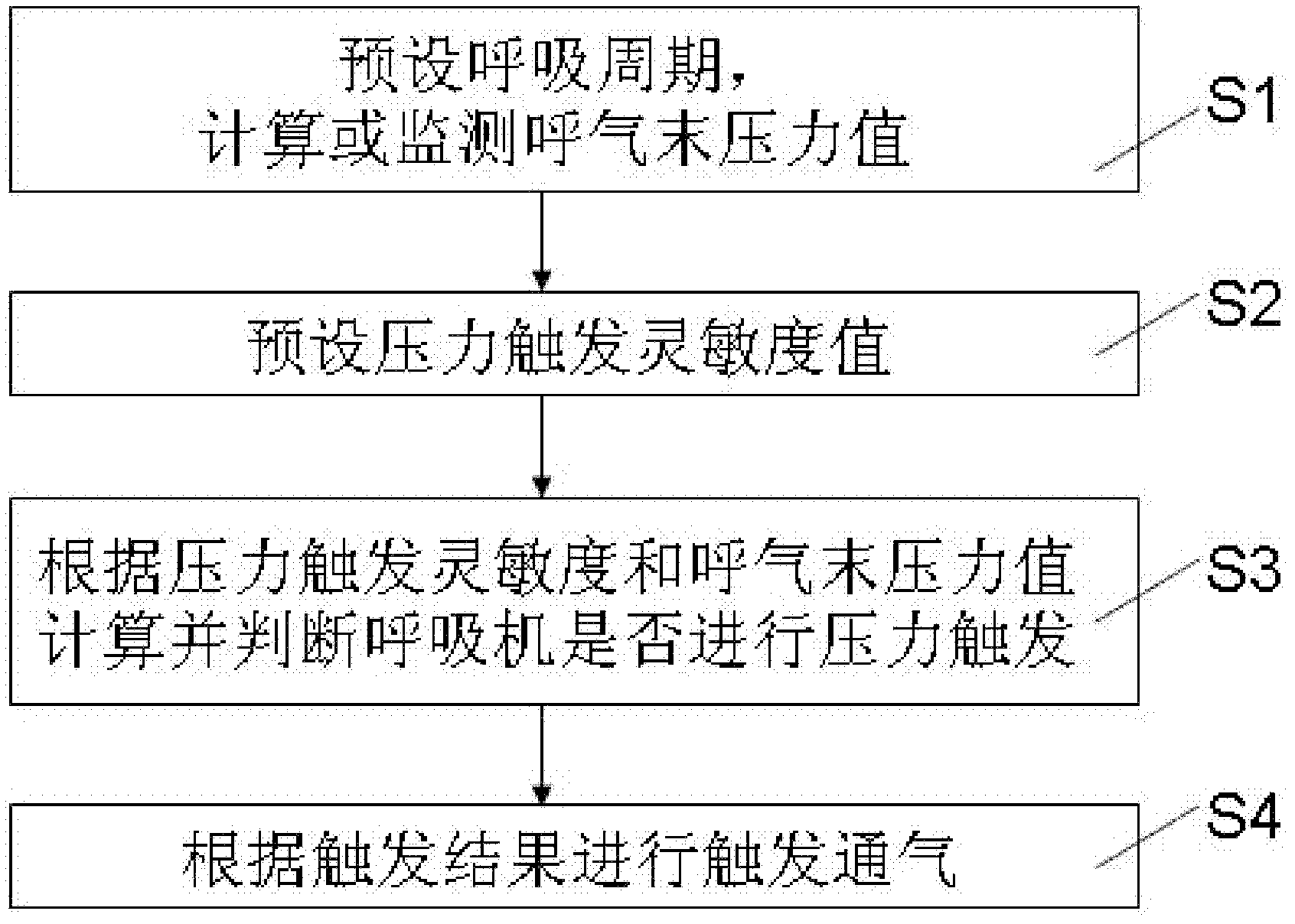
The invention discloses a pressure trigger control method for a breathing machine. The method comprises the steps as follows: S1, presetting a breathing cycle and calculating or monitoring an end-expiratory pressure value; S2, presetting a pressure trigger sensitivity value; S3, calculating and judging if the breathing machine is subjected to pressure trigger according to the pressure trigger sensitivity value and the end-expiratory pressure value; and S4, triggering for ventilation according to a triggering result. The method can reduce false triggering operations through an algorithm, can enable a patient to more easily trigger the breathing machine when PEEPI (positive end-expiratory pressure) is existent in a breathing system, and is suitable for pressure trigger control systems of an anesthesia machine and the like at the same time.

Description

technical field [0001] The invention relates to the field of ventilator trigger control, in particular to a method for ventilator pressure trigger control. Background technique [0002] Ventilator is a device that can replace, control or change people's normal physiological breathing, increase lung ventilation, improve respiratory function, reduce breathing work consumption, and save heart reserve capacity. Ventilators are more and more widely used in the fields of first aid, anesthesia, ICU and respiratory therapy, and have become an indispensable device in clinical treatment. [0003] According to the working characteristics of the ventilator, it can be divided into constant pressure type, timing type, constant volume type and constant flow type. At present, high-end ventilators can generally be triggered by pressure and flow rate. The ventilator is most commonly triggered by pressure, and the sensitivity of pressure trigger depends on the type of pressure sensor and the...

Claims


Application Information

Patent Timeline
IPC IPC(8): A61M16/00
Inventor 金文贤
Owner BEIJING AEONMED
Learn More