Control system and control method of compression pump for oxygenerator

A control system and compression pump technology, applied in pump control, mechanical equipment, machine/engine, etc., can solve problems such as failure to start normally, start speed mismatch, etc., to achieve improved service life mismatch, rapid response, and precise control Effect

Active Publication Date: 2013-07-03
BEIJING AEONMED
View PDF8 Cites 0 Cited by
  • Summary
  • Abstract
  • Description
  • Claims
  • Application Information

AI Technical Summary

Problems solved by technology

[0007] The object of the present invention is to provide a control system and control method for a compressor pump used in an oxygen generator, which satisfies the need for two compressor pumps to start up alternately in a plain environment and two compressor pumps to work simultaneously in a plateau environment. Mode switching, and effectively solve the problem that one of the two compressors cannot be started normally due to the mismatch of starting speed or the pressure of the gas circuit when the two compressors are started at the same time, so that the entire gas circuit system can run normally and safely and switch

Method used


Image

  • Control system and control method of compression pump for oxygenerator
  • Control system and control method of compression pump for oxygenerator
  • Control system and control method of compression pump for oxygenerator

Examples


Embodiment 1

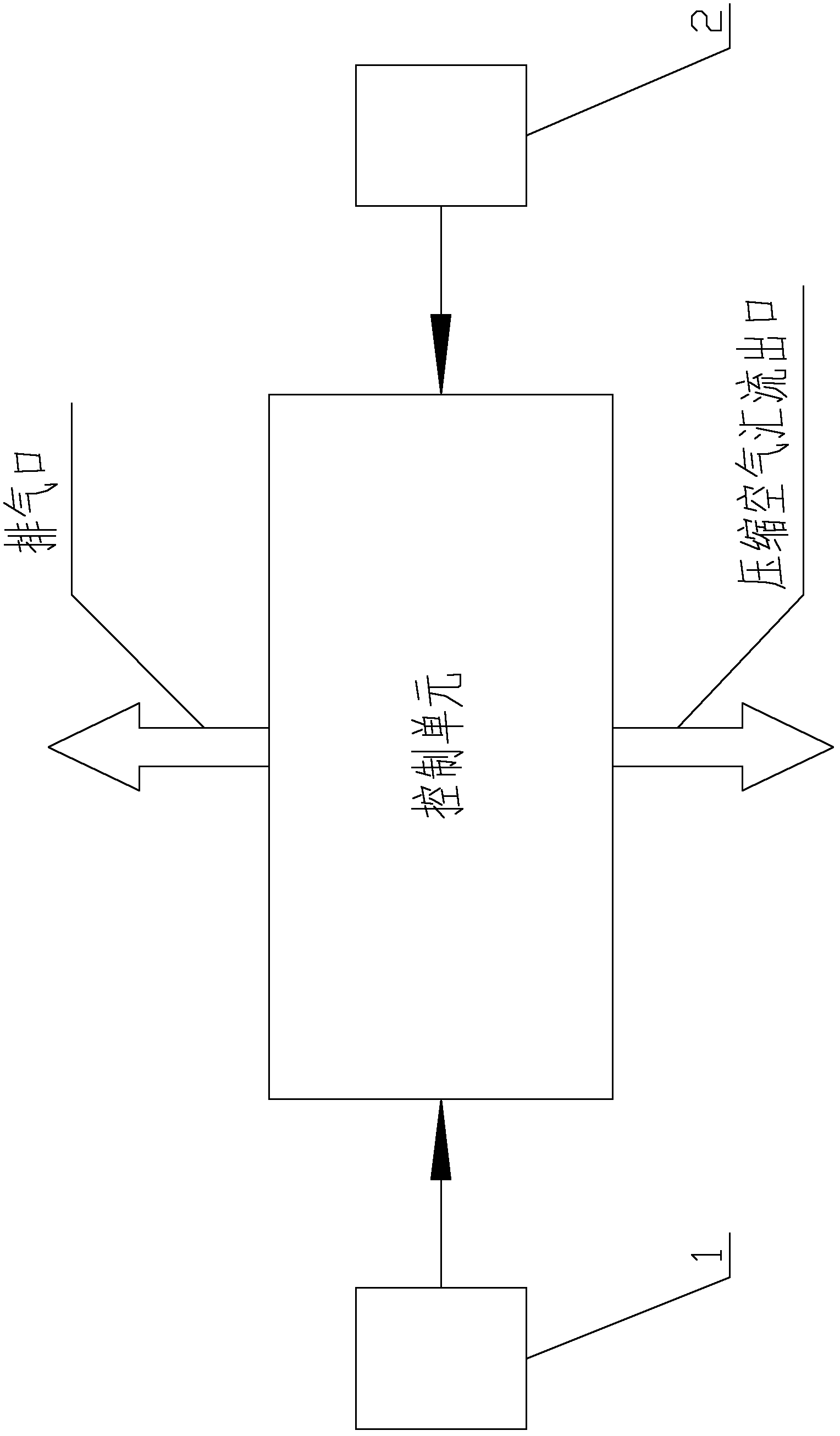
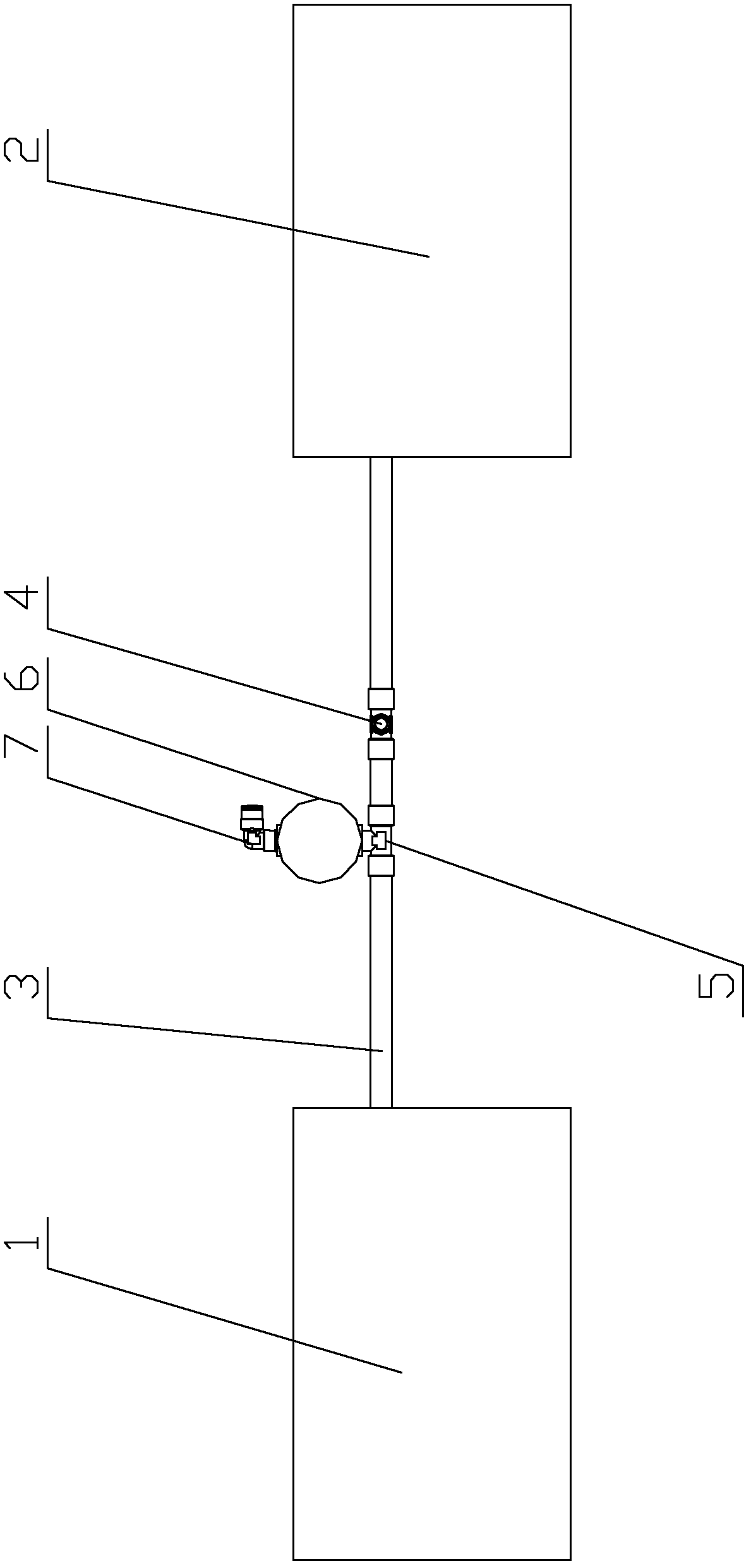
[0039] Such as figure 1 , 2 As shown, in a preferred embodiment of the present invention, the oxygen generator compressor pump control system includes two identical first compressor pumps 1, second compressor pumps 2 and control units, and the first compressor pump A silicone tube 3 is installed between the output end of 1 and the output end of the second compression pump 2, and the first three-way pipe joint 4 is installed on the silicone tube 3, and it is used as a compressed air converging outlet. On the silicone tube 3 on the left side of 4, that is, close to the first compression pump 1, a second three-way pipe joint 5 is installed, and a two-position two-way solenoid valve 6 is installed at its exhaust port, and a two-position two-way solenoid valve 6 is installed. The valve 6 is equipped with a push-in joint 7 that can turn back and is used as an exhaust port.

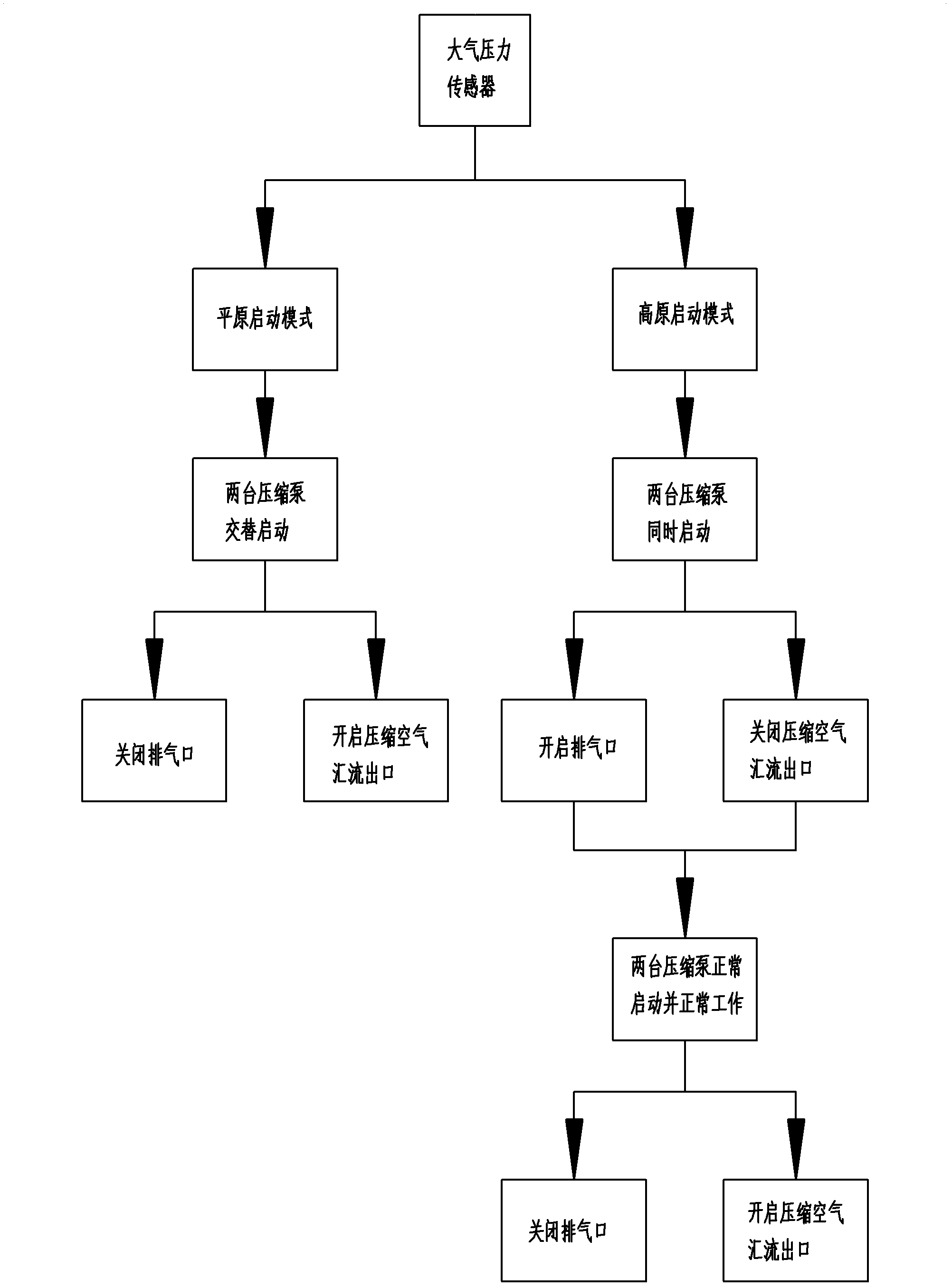
[0040] At the same time, the barometric pressure sensor is included in the control unit.

[0041] When wor...

Embodiment 2

[0045] Such as figure 1 , 3 As shown, in a preferred embodiment of the present invention, the oxygen generator compressor pump control system includes two identical first compressor pumps 1, second compressor pumps 2 and control units, and the first compressor pump A silicone tube 3 is installed between the output end of 1 and the output end of the second compression pump 2, and the first three-way pipe joint 4 is installed on the silicone tube 3, and it is used as a compressed air converging outlet. On the silicone tube 3 on the right side of 4, that is, near the second compression pump 2, a second three-way pipe joint 5 is installed, and a two-position two-way solenoid valve 6 is installed at its exhaust port, and a two-position two-way solenoid valve The valve 6 is equipped with a push-in joint 7 that can turn back and is used as an exhaust port.

[0046] At the same time, the barometric pressure sensor is included in the control unit.

[0047] When working, after the ox...


PUM


Abstract

The invention discloses a control system and a control method of a compression pump for an oxygenerator. Output ends of two same compression pumps are connected through a pipeline; a compressed air confluence outlet is formed in the pipeline; an air discharge opening which can be closed is formed in any one side of the pipeline; the two compression pumps are controlled by a control unit to be alternatively started or simultaneously started and the air discharge opening and the compressed air confluence outlet are controlled to be opened or closed, so that the oxygenerator is normally used in plateau and plain, and moreover the problem that one of the two compression pumps cannot be normally started as the starting speeds do not match or an air path has pressure when the two compression pumps are simultaneously started is solved, and a whole air path system can be normally and safely operated and switched.

Description

technical field [0001] The invention relates to a control system and a control method for a compressor pump used in an oxygen generator, in particular to a control system and a control method that can satisfy the normal start-up of a compressor pump used in an oxygen generator in plateau and plain areas. Background technique [0002] In recent years, with the rapid development of medical technology, the types of medical devices have also increased, and are constantly being improved and perfected. For example: Asthma patients and patients with dyspnea symptoms often use oxygen concentrators for assisted breathing. [0003] At present, the working principle of the common oxygen generator is: the use of molecular sieve physical adsorption and desorption technology. That is to fill the molecular sieve in the oxygen generator, and use it to absorb nitrogen in the air when it is pressurized, and the remaining unabsorbed oxygen is collected, and after purification, it becomes high...

Claims


Application Information

Patent Timeline
Patent Type & Authority Applications(China)
IPC IPC(8): F04B49/06F04B49/00
Inventor 吴满立滕丹杰
Owner BEIJING AEONMED
Why Eureka
Try Eureka