Directly heating machine

A direct heat engine and evaporator technology, applied in the field of heat exchange, can solve the problems that medium and high temperature wastewater heat exchangers cannot be used, and cannot be solved well.

Inactive Publication Date: 2013-07-03
HIT HARBIN INST OF TECH KINT TECH
View PDF7 Cites 9 Cited by
  • Summary
  • Abstract
  • Description
  • Claims
  • Application Information

AI Technical Summary

Problems solved by technology

[0010] The working conditions of medium and high temperature wastewater heat exchangers are very different from ordinary heat exchangers. The design method and experience of ordinary heat exchangers cannot be used for medium and high temperature

Method used


Image

  • Directly heating machine
  • Directly heating machine
  • Directly heating machine

Examples


Embodiment Construction

[0029] The present invention will be described in further detail below in conjunction with the accompanying drawings and embodiments.

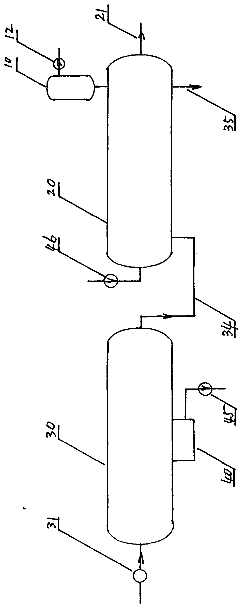
[0030] figure 1 The system diagram of the direct heat engine embodiment of the present invention is provided, and the direct heat engine system is described as follows according to the flow process:

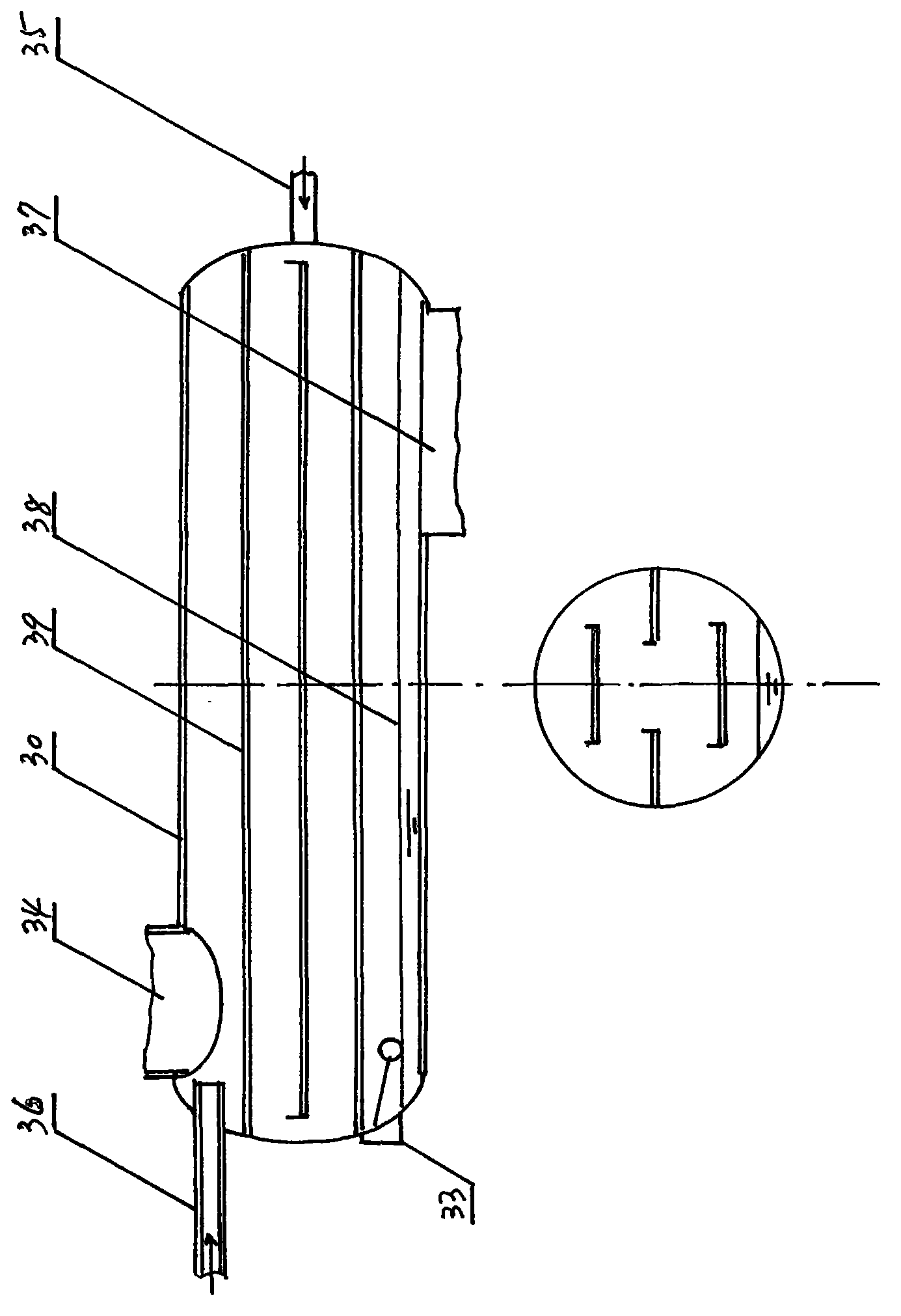
[0031] 1. Medium and high temperature waste water enters the evaporator 30 through the water inlet pipe, and there is a water inlet regulating valve 31 on the water inlet pipe;

[0032] 2. The pressure in the evaporator 30 is lower than the saturation pressure corresponding to the temperature of the incoming medium-high temperature wastewater, so the medium-high temperature wastewater is partially evaporated immediately after entering the evaporator, which is also called flash evaporation or capacity expansion;

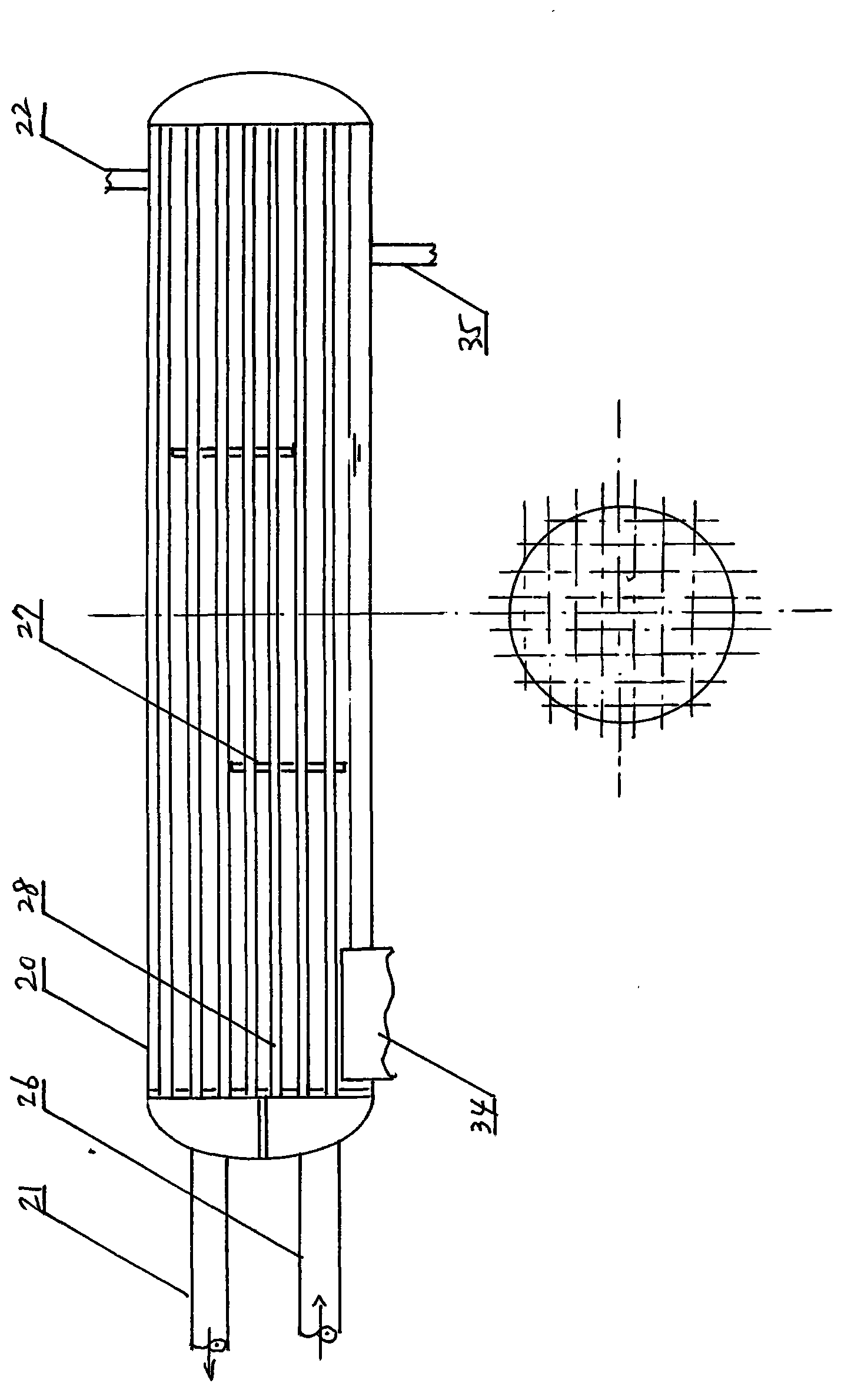
[0033] 3. The steam generated in the evaporator 30 enters the condenser 20 through the steam delivery channel 34;

[0034] 4. The rem...


PUM


Abstract

The invention provides a directly heating machine which structurally comprises an evaporator, a condenser, a deaeration device and an anti-cavitation device. Medium-high temperature wastewater is flashed in the evaporator to produce steam; a steam passage is arranged between the evaporator and the condenser; and steam condenses to give out heat in the condenser. The deaeration device is connected to a part above the condenser, and the anti-cavitation device is connected to a water outlet below the evaporator. The evaporator is a horizontal pressure vessel; and the condenser is a horizontal shell and tube exchanger. The deaeration device structurally comprises an air collector and a vacuum pump. The anti-cavitation device structurally comprises a water suction pump, a water jet pump, a nozzle and a diffuser pipe. Residual saturated wastewater after flashing in the evaporator flows into a pressurizer; the nozzle in the pressurizer is connected with a water jet pipe and the water jet pump; and the diffuser pipe in the pressurizer is connected with a water outlet pipe and the air suction pump. The nozzle in the pressurizer jets at a high speed, and jet waterflow and saturated wastewater are mixed and flow together into the diffuser pipe to be subjected to deceleration and pressurizing to be changed into unsaturated water to be drained by the water suction pump.

Description

technical field [0001] The invention relates to heat exchange technology, in particular to a direct heat engine. Background technique [0002] my country is already a big country in steel production, and the annual output of steel accounts for 40% of the world's total output. Whether it is steelmaking or ironmaking, a large amount of slag will be produced. Slag is produced along with iron and steel. It is a by-product of iron and steel smelting, and it is also the basic condition for a series of important metallurgical reactions. It directly participates in the physical and chemical reactions and mass and heat transfer processes of iron and steel smelting. It not only affects the output of iron and steel, quality, and is closely related to the consumption of raw materials and energy. [0003] In iron and steel metallurgical furnaces, high-temperature slag at 1400-1500°C is produced. After flowing out through the slag mouth, and then entering the slag flushing launder throu...

Claims


Application Information

Patent Timeline
IPC IPC(8): F24D17/00F22B3/04C02F1/06
Inventor 尚德敏李金峰李伟
Owner HIT HARBIN INST OF TECH KINT TECH
Why Eureka
Try Eureka