Control device for internal combustion engine and method for controlling internal combustion engine

a control device and internal combustion engine technology, applied in the direction of electric control, machines/engines, instruments, etc., can solve the problems of large deviation of actual operation point from set operation point, engine damage risk, operation point, etc., to achieve optimal fuel efficiency, optimal fuel efficiency, learning variation factors

Active Publication Date: 2013-10-24
MITSUBISHI ELECTRIC CORP
View PDF4 Cites 45 Cited by
  • Summary
  • Abstract
  • Description
  • Claims
  • Application Information

AI Technical Summary

Benefits of technology

[0013]Therefore, according to the present invention, in the internal combustion engine provided with the supercharger including the wastegate valve, the control of the acceleration response characteristics, the operation at the optimal fuel efficiency point, and the learning of the variation factors can be performed.

Problems solved by technology

The turbocharger has a risk of damaging the engine due to a supercharging pressure which becomes higher than needed when the turbine is rotated at a high rpm under a high load.
Therefore, there arises a problem in that an actual operation point greatly deviates from a set operation point.
Thus, there is another problem in that an operation point, at which the optimal fuel efficiency is obtained, cannot be known.
Thus, even in this case, there is a problem in that the setting of the ignition timing and an air / fuel ratio is required to be changed.

Method used


Image

  • Control device for internal combustion engine and method for controlling internal combustion engine
  • Control device for internal combustion engine and method for controlling internal combustion engine
  • Control device for internal combustion engine and method for controlling internal combustion engine

Examples


first embodiment

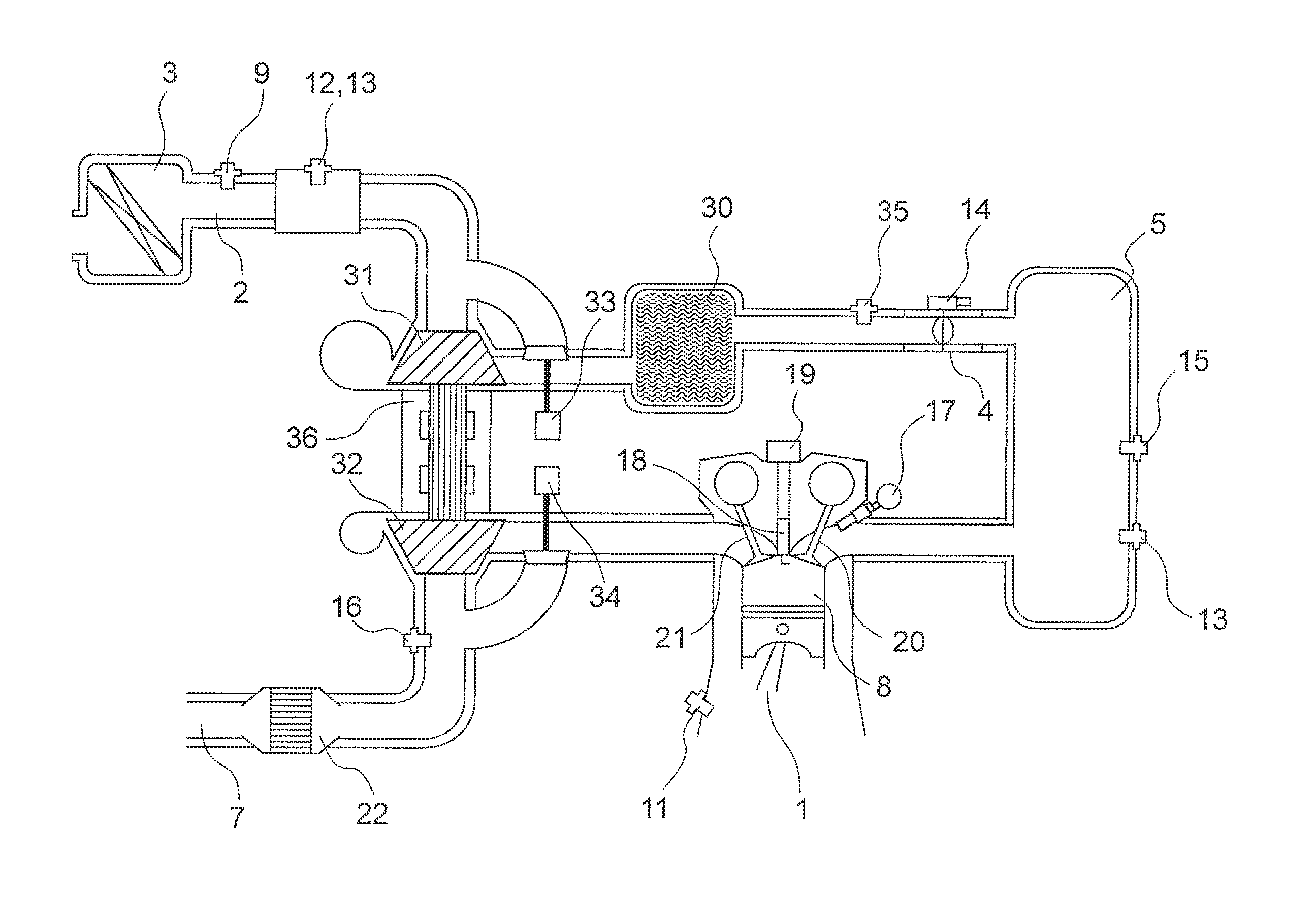
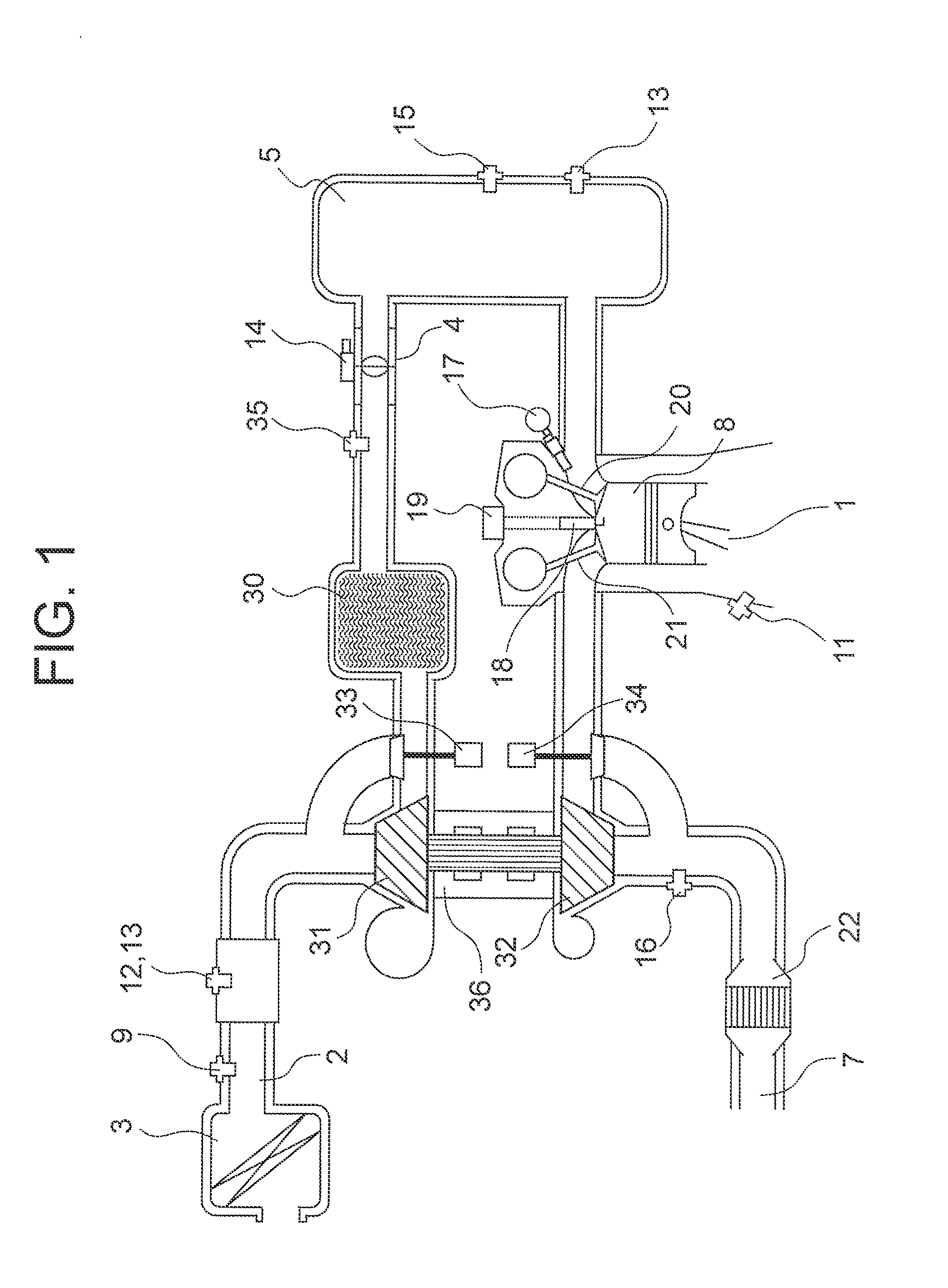
[0025]FIG. 1 is a configuration diagram illustrating an intake / exhaust system of an internal combustion engine according to the present invention. In FIG. 1, a crank-angle sensor 11 for generating an electric signal in accordance with a rotation angle of a crank of an internal combustion engine (hereinafter, also referred to simply as “engine”) 1 is mounted to the crank. An intake pipe 2 forming an intake path is connected to an inlet port of a combustion chamber of the engine 1, whereas an exhaust pipe 7 forming an exhaust path is connected to an outlet port of the combustion chamber.

[0026]An air cleaner 3 for purifying intake outside air is mounted to the intake pipe 2 on an upstream side thereof (opposite to the side where the engine 1 is provided). An airflow sensor 12 and an intake-air temperature sensor 13 are mounted integrally or separately to the intake pipe 2 on a downstream side (on the side where the engine 1 is provided) of the air cleaner 3. The airflow sensor 12 gener...


PUM


Abstract

Provided is a control device for an internal combustion engine, capable of controlling acceleration-response characteristics, performing an operation at an optimal fuel-efficiency point, and learning variation factors in an internal combustion engine provided with a supercharger including a wastegate valve. A target throttle-valve upstream pressure is calculated based on a target charging efficiency and a rotation speed. An exhaust-gas flow rate is calculated based on an air / fuel ratio and an intake-airflow rate. A target compressor driving force is calculated based on a target intake-airflow rate and a target throttle-valve upstream pressure. A wastegate-valve control value is calculated from the exhaust-gas flow rate and the target compressor driving force by using the relationship in which the relation expression expressing the characteristics of the exhaust-gas flow rate and the target compressor driving force depends only on the wastegate-valve control value.

Description

BACKGROUND OF THE INVENTION[0001]1. Field of the Invention[0002]The present invention relates to a control device for an internal combustion engine, for controlling an internal combustion engine provided with a supercharger which includes a turbine provided to an exhaust path and a compressor provided to an intake path.[0003]2. Description of the Related Art[0004]Conventionally, there is known a turbocharger including a supercharger to be mounted to an intake path of an internal combustion engine (hereinafter, referred to simply as “engine”), which is achieved for the purpose of improving an output of the engine. The supercharger moves a turbine by rotating the turbine with an exhaust gas. The turbocharger has a risk of damaging the engine due to a supercharging pressure which becomes higher than needed when the turbine is rotated at a high rpm under a high load. Therefore, in general, an exhaust-gas bypass path is provided at upstream of the turbine so as to divert a part of the ex...

Claims


Application Information

Patent Timeline
Patent Type & Authority Applications(United States)
IPC IPC(8): F02B37/12F02D41/26F02D23/02
CPCF02B33/44F02B37/16F02B37/18F02B39/16F02D23/02F02D41/0007F02D41/18F02D2200/0406F02D2200/0414Y02T10/12
Inventor WATANUKI, TAKUOHAGARI, HIDEKI
Owner MITSUBISHI ELECTRIC CORP
Why Eureka
Try Eureka