
Digital oscilloscope with front end attenuation function

A digital oscilloscope and functional technology, applied in the direction of digital variable display, etc., can solve the problems of difficult procurement, increased cost, and inconsistent bandwidth of the vertical gear of digital oscilloscope 1, and achieve the effect of simple structure and easy realization

Active Publication Date: 2013-07-03
RIGOL
View PDF5 Cites 10 Cited by
  • Summary
  • Abstract
  • Description
  • Claims
  • Application Information

AI Technical Summary

Problems solved by technology

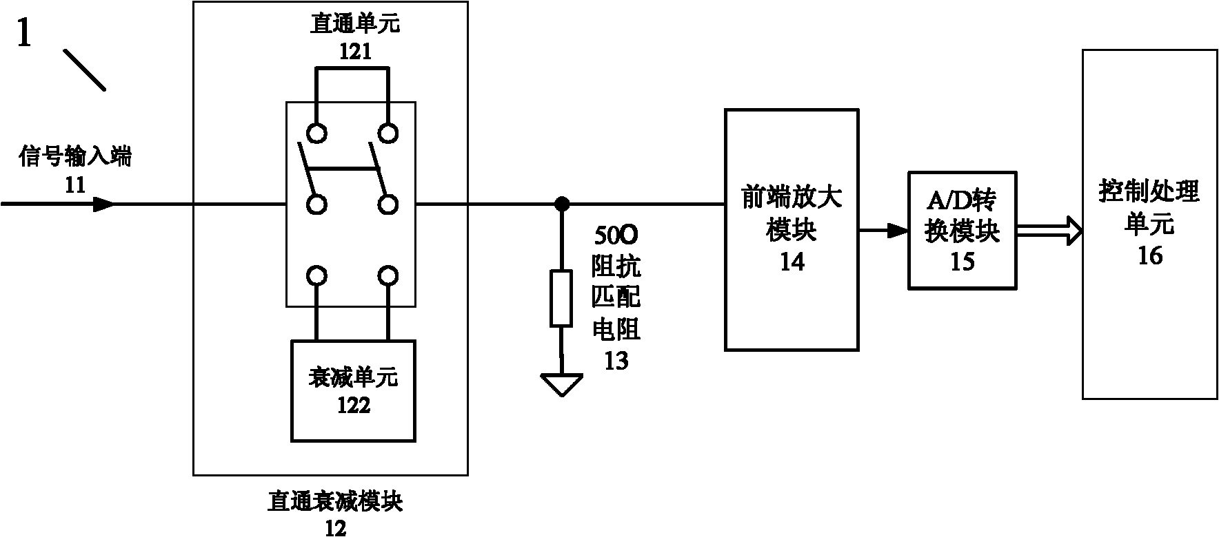
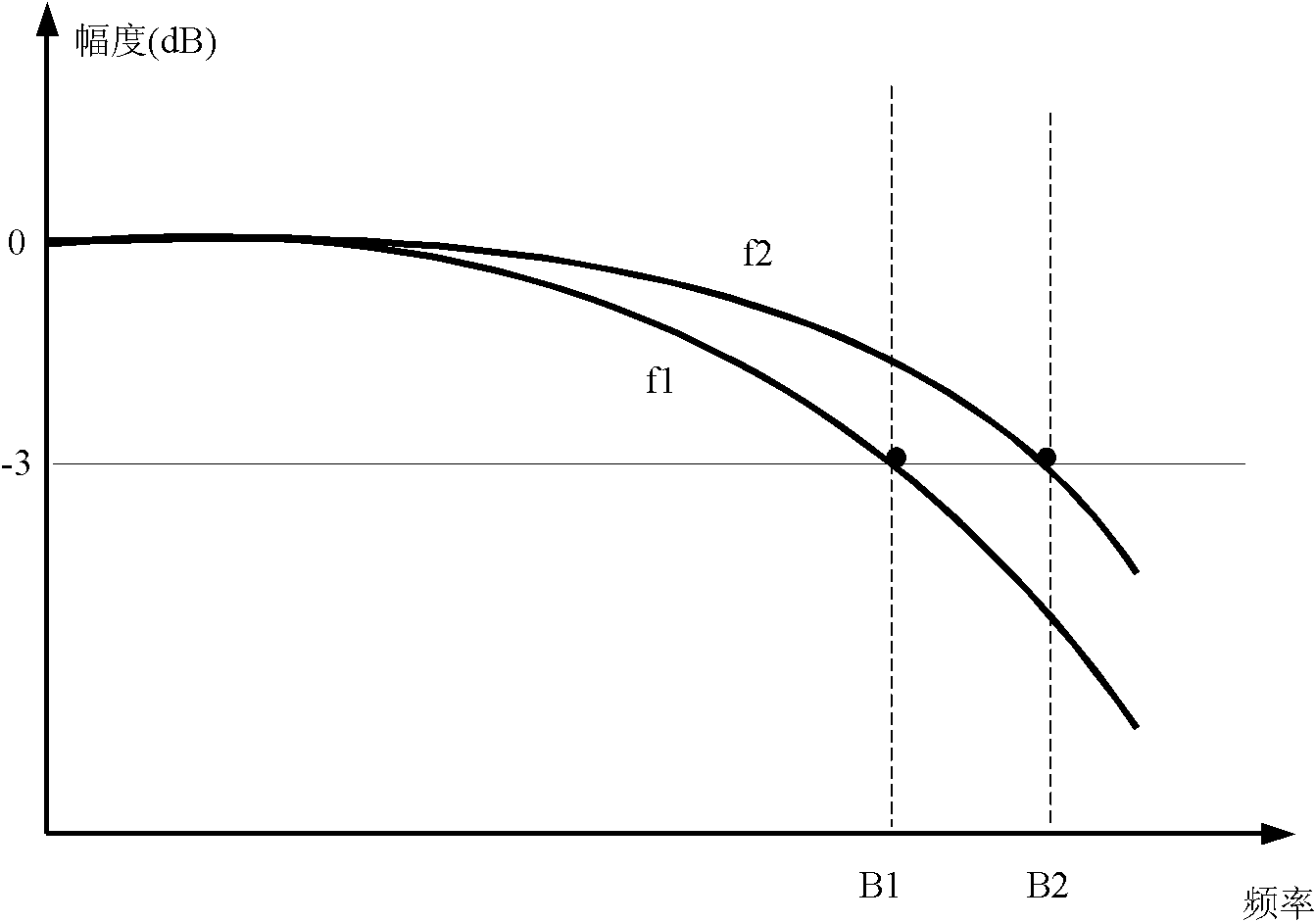
[0003] combined reference figure 1 and figure 2 , in the prior art, when the high-frequency signal enters the through-attenuation module 12 through the signal input terminal 11, due to reasons such as input insertion loss of the attenuation unit 122, the frequency response curve f1 of the attenuation unit 122 to the high-frequency signal is different from that of the through-unit 121 The frequency response curve f2 to high-frequency signals is inconsistent, from figure 2 It can be seen from the figure that when the amplitude is -3dB, the bandwidth B1 of f1 is smaller than the bandwidth B2 of f2, which leads to the inconsistency of the vertical scale bandwidth of the digital oscilloscope 1. In order to solve the above problems, it is necessary to choose a high-bandwidth attenuation relay or an attenuator , but such an attenuating relay or attenuating sheet is not only expensive, but also difficult to purchase, so this method increases the cost and is not easy to implement

Method used


Image

  • Digital oscilloscope with front end attenuation function
  • Digital oscilloscope with front end attenuation function
  • Digital oscilloscope with front end attenuation function

Examples


Embodiment Construction

[0020] A preferred embodiment of the present invention will be introduced below in conjunction with the accompanying drawings.

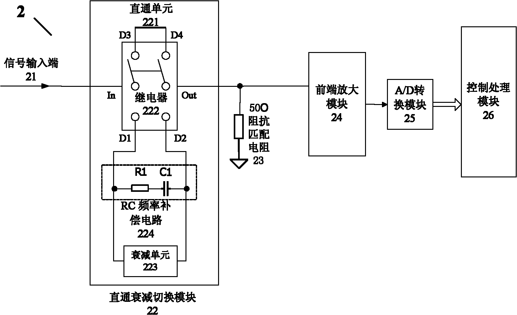
[0021] refer to image 3 , the digital oscilloscope 2 includes a signal input terminal 21 sequentially connected in series, a straight-through attenuation switching module 22, a 50 ohm impedance matching resistor 23, a front-end amplification module 24, an A / D conversion module 25 and a control processing module 26, and the signal input terminal 21 is used for Receive the analog signal to be tested, and the direct attenuation switching module 22 is used to perform attenuation control on the analog signal to be measured. The direct attenuation switching module 22 includes a direct unit 221 and an attenuation unit 223. When the user inputs a small vertical gear, the control processing module 26 adjusts the The set vertical gear, the control signal input terminal 21 is connected to the through unit 221, and the signal is directly output to the impedance...


PUM


Abstract

The invention discloses a digital oscilloscope with a front end attenuation function, which comprises a signal input end, a straight-through attenuation switching module, a front end amplification module, an A / D (analog / digital) conversion module and a control processing module that are connected in series sequentially, wherein the straight-through attenuation switching module responses to a control signal of the control processing module; an attenuation unit is connected between the signal input end and the front end amplification module; the digital oscilloscope further comprises an RC (resistor-capacitor) frequency compensation circuit; the straight-through attenuation switching module responses to the control signal of the control processing module; and the attenuation unit and the RC frequency compensation circuit are connected between the signal input end and the front end amplification module in parallel. According to the digital oscilloscope, under the condition that the cost is not increased, the bandwidths of vertical gears at high frequency are basically the same, and the digital oscilloscope is simple in structure and easy to realize.

Description

technical field [0001] The invention relates to the field of digital oscilloscopes, in particular to a digital oscilloscope with a front-end attenuation function. Background technique [0002] refer to figure 1 In the prior art, a digital oscilloscope 1 usually includes a signal input terminal 11, a through attenuation switching module 12, a 50 ohm impedance matching resistor 13, a front-end amplification module 14, an A / D conversion module 15 and a control processing module 16 connected in series in sequence, The signal input terminal 11 receives the analog signal to be tested, and the direct attenuation module 12 is used for attenuation control of the analog signal to be tested. The direct attenuation switching module 12 includes a direct unit 121 and an attenuation unit 122. When the user inputs a small vertical gear, the control processing module 16 According to the vertical gear set by the user, the control signal input terminal 11 is connected to the through unit 121,...

Claims


Application Information

Patent Timeline
IPC IPC(8): G01R13/02
Inventor 史慧王悦王铁军李维森
Owner RIGOL
Learn More