Wireless interference testing method for electromagnetic compatibility dark room

An electromagnetic compatibility anechoic chamber and wireless interference technology, applied in the direction of measuring interference from external sources, measuring electricity, electrical components, etc., can solve the problem of extremely high site accuracy, low detection accuracy of horizontal antennas, and difficulty in ensuring dual-antenna test systems Accuracy and efficiency and other issues, to achieve the effect of improving accuracy and efficiency

Inactive Publication Date: 2013-07-03
HONG FU JIN PRECISION IND (SHENZHEN) CO LTD +1
View PDF0 Cites 4 Cited by
  • Summary
  • Abstract
  • Description
  • Claims
  • Application Information

AI Technical Summary

Problems solved by technology

However, the double-antenna test has extremely high requirements on the accuracy of the site. The previous EMC darkroom test method used signal sources to verify the antenna measurement system in the vertical and horizontal directions respectively. less accurate
Therefore, it is difficult to guarantee the accuracy and efficiency of the dual-antenna test system in the EMC darkroom

Method used


Image

  • Wireless interference testing method for electromagnetic compatibility dark room
  • Wireless interference testing method for electromagnetic compatibility dark room

Examples


Embodiment Construction

[0016] The present invention will be further described in detail below in conjunction with the accompanying drawings.

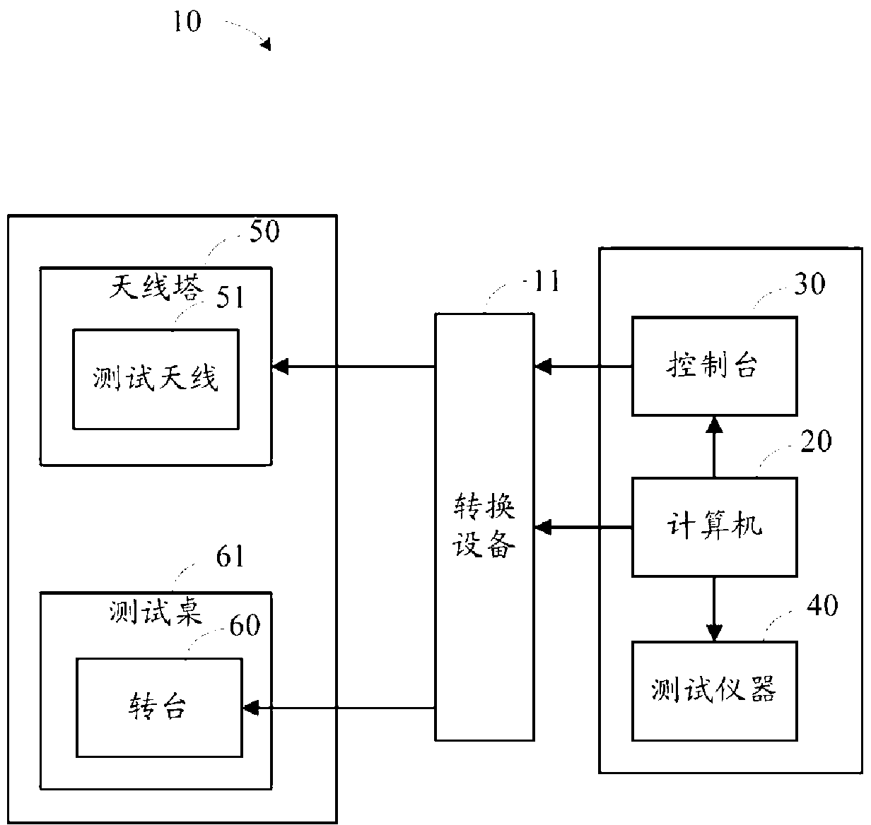
[0017] See figure 1 , is a schematic diagram of an EMC darkroom testing system according to an embodiment of the present invention. The test system 10 includes a computer 20 , a console 30 , and test instruments 40 located in the operating room, and an antenna tower 50 and a turntable 60 located in the darkroom. A test antenna 51 for testing is mounted on the antenna tower 50 , and the turntable 60 is usually located on a test table 61 . The computer 20, console 30 and testing instrument 40 in the operating room are connected with the turntable 60 and the antenna tower 50 in the darkroom through the conversion device 11, and can move and control the positions of the turntable 60 and the antenna tower 50 in the darkroom. The computer 20 in the operating room can control the turntable 60 and the antenna tower 50 through the test software and the console 30 , ...


PUM


Abstract

The invention discloses a wireless interference testing method for an electromagnetic compatibility dark room. A computer and a control platform are connected with a testing antenna and a rotary table which are arranged in the electromagnetic compatibility dark room. The wireless interference testing method for the electromagnetic compatibility dark room includes that a computer responses to the operation of an operator so that a noise bandwidth threshold value is set; a signal source is added to the electromagnetic compatibility dark room, the computer and the control platform response to the operation of the operator so that the testing antenna is controlled to be arranged at a preset height, the direction of polarization of the testing antenna is adjusted to be a vertical direction, and the rotary table is further controlled to be arranged at a preset angle, the environmental noise of the electromagnetic compatibility dark room is measured to be used as a first measuring result, a first noise bandwidth value is determined according to the first measuring result, and the first noise bandwidth value is compared with a threshold value so that the wireless interference intensity of the electromagnetic compatibility dark room is determined. According to the wireless interference testing method for the electromagnetic compatibility dark room, a testing system is used for adjusting the direction of the polarization and the height of the testing antenna in the dark room by the operator, the wireless interference of the dark room is tested, and signal sources need not to be used respectively to test the testing antenna with different directions of the polarization. Therefore, the testing precision and the testing efficiency can be improved.

Description

technical field [0001] The invention relates to the technical field of electromagnetic compatibility (EMC) testing, in particular to a wireless interference testing method used in an electromagnetic compatibility darkroom. Background technique [0002] The EMC darkroom is a very important test facility for the design and testing of electromagnetic compatibility of electronic products. Because the EMC darkroom is easy to use and economical, most electronic products are tested for electromagnetic compatibility improvement during the design period, and the final electromagnetic compatibility compliance The tests are all carried out in the EMC darkroom. [0003] The existing EMC darkroom adopts dual-antenna test to improve test efficiency. However, the double-antenna test has extremely high requirements on the accuracy of the site. The previous EMC darkroom test method used signal sources to verify the antenna measurement system in the vertical and horizontal directions respect...

Claims


Application Information

Patent Timeline
Patent Type & Authority Applications(China)
IPC IPC(8): G01R31/00H04B17/00
CPCG01R29/0814G01R29/0821G01R31/001G01R35/00H04B17/345
Inventor 杨永升
Owner HONG FU JIN PRECISION IND (SHENZHEN) CO LTD
Why Eureka
Try Eureka