Projection system of immersed photolithography system

An immersion lithography and projection system technology, applied in the field of projection systems, can solve problems such as residual water droplets, missing or distorted edges of photoresist layer graphics, and affecting the quality of edge imaging of projection systems, so as to prevent overflow and ensure integrity Effect

Active Publication Date: 2013-07-03
SEMICON MFG INT (SHANGHAI) CORP
View PDF5 Cites 1 Cited by
  • Summary
  • Abstract
  • Description
  • Claims
  • Application Information

AI Technical Summary

Problems solved by technology

However, the interaction between the gas curtain and the liquid in the liquid pool will generate aerosol, which will overflow from the edge of the projection system; especially when the scanning speed of the system continues to increase, it is more likely to cause the photoresist on the wafer or the coating on the photoresist surface Water droplets remain on the surface, which affects the quality of the edge imaging of the projection system of the immersion lithography system, and then causes the edge of the photoresist layer to be missing or distorted before or after exposure to the photoresist layer

Method used


Image

  • Projection system of immersed photolithography system
  • Projection system of immersed photolithography system
  • Projection system of immersed photolithography system

Examples


Embodiment 1

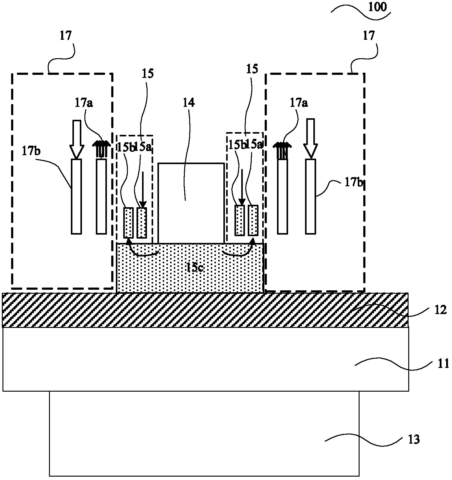
[0048] figure 2 It is a structural schematic diagram of the first embodiment of the projection system of the immersion lithography system of the present invention; image 3 It is a top view structure diagram of the first embodiment of the projection system of the immersion lithography system of the present invention.

[0049] to combine figure 2 and image 3 , The projection system 200 includes: a projection lens 140 , a liquid pool 150 c , a liquid supply device 150 , a first gas shower device 170 , a second gas shower device 180 and a suction device 190 .

[0050] Wherein, the projection lens 140 is used to scale down and project the pattern on the reticle onto the photoresist layer 120 on the semiconductor substrate 110 .

[0051] The liquid pool 150c is located in the exposure field of the projection lens 140 as the exposure medium of the projection lens 140; the projection lens 140 is immersed in the liquid pool 150c.

[0052] The liquid supply device 150 is located o...

Embodiment 2

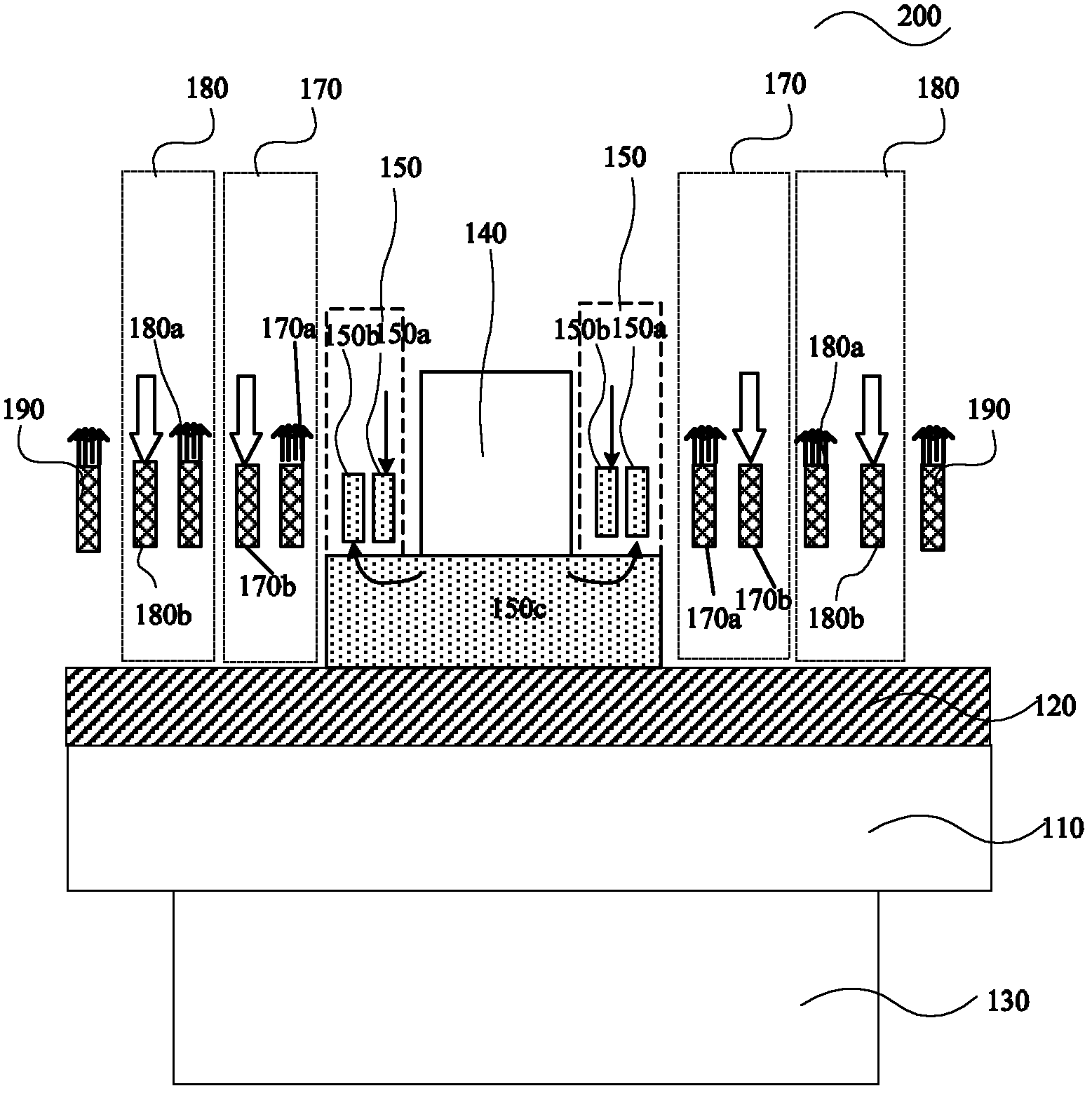
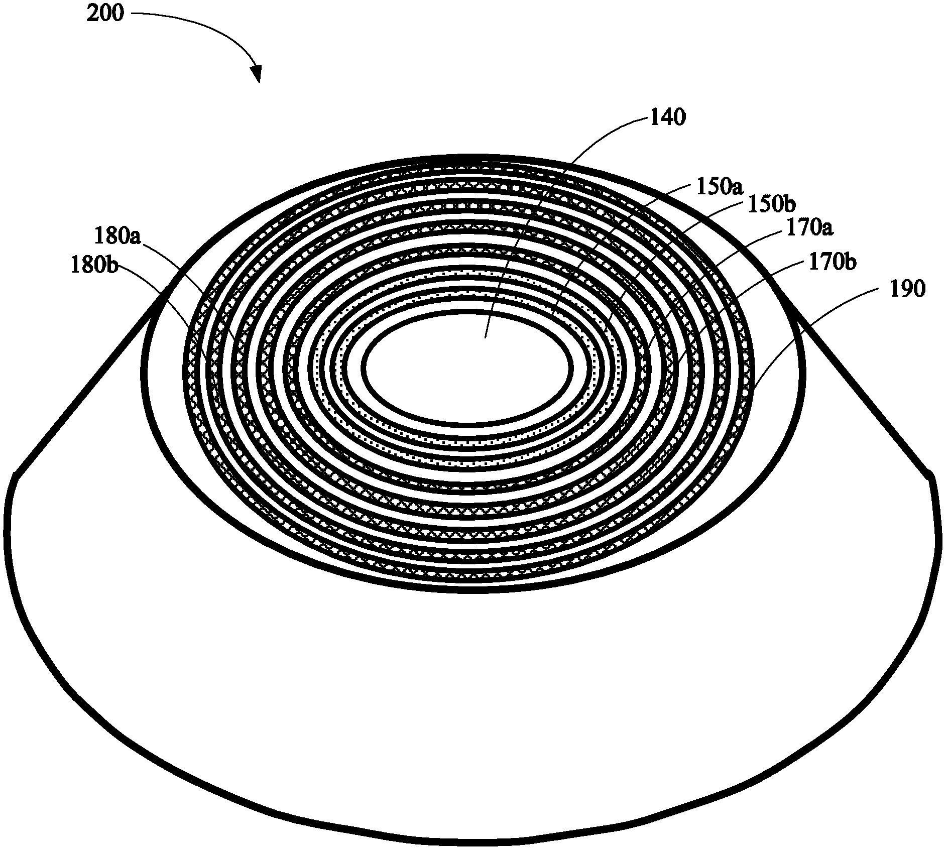
[0068] Figure 4 It is a structural schematic diagram of the second embodiment of the projection system of the immersion lithography system of the present invention.

[0069] like Figure 4 As shown, the projection system 300 includes: a projection lens 240 , a liquid pool 250 c , a liquid supply device 250 , a first gas shower device 270 , a second gas shower device 280 , a third gas shower device 290 and a suction device 260 .

[0070] Wherein, the projection lens 240 is used to scale down and project the pattern on the reticle onto the photoresist layer 220 on the semiconductor substrate 210 .

[0071] The liquid pool 250c is located in the exposure field of the projection lens 240 as the exposure medium of the projection lens 240; the projection lens 240 is immersed in the liquid pool 250c.

[0072] The liquid supply device 250 is located on the periphery of the projection lens, and is used for supplying liquid into the liquid pool 250c. The liquid supply device 250 inc...


PUM

PropertyMeasurementUnit
refractive indexaaaaaaaaaa

Abstract

A projection system of an immersed photolithography system comprises a projection lens, a liquid cell located in an exposure field of the projection lens and taken as an exposure medium of the projection lens, a liquid supply device located at the periphery of the projection lens and used for providing the liquid cell, at least two gas spraying devices sequentially distributed at the periphery of the liquid supply device, and a suction device located at the periphery of the outermost gas spraying device. The projection system effectively prevents liquid and gas from overflowing from the edge of the projection system, avoids the affect of gas on quality of edge imaging of the immersed photolithography system, and ensures the completeness of images on a photoresist layer.

Description

technical field [0001] The invention relates to the technical field of semiconductors, in particular to a projection system of an immersion photolithography system. Background technique [0002] In the semiconductor industry, in order to make smaller transistors in order to form more gates on a chip and make higher performance transistors, photolithography must use shorter wavelengths of light to form smaller feature sizes, it is predicted 193nm immersion lithography technology will replace 157nm lithography technology to become a new generation of lithography technology for semiconductor production below 45nm. [0003] Although immersion lithography has received a lot of attention, it still faces great challenges. According to the lithography content of the 2005 edition of "International Semiconductor Technology Blueprint", the challenges of immersion lithography are: (a) control of defects due to immersion environment, including air bubbles and contamination; Compatibili...

Claims


Application Information

Patent Timeline
Patent Type & Authority Applications(China)
IPC IPC(8): G03F7/20
Inventor 伍强郝静安
Owner SEMICON MFG INT (SHANGHAI) CORP
Why Eureka
Try Eureka