Circuit structure for controlling infrared remote control emission

A circuit structure and infrared remote control technology, applied in non-electrical signal transmission systems, signal transmission systems, instruments, etc., can solve the problems of unavoidable procurement costs of triodes and current-limiting resistors, occupation of processing capacity, and control of unfavorable costs. Stable and reliable working performance, low power consumption, flexible effect development

Active Publication Date: 2013-07-03
CRM ICBG (WUXI) CO LTD
View PDF6 Cites 7 Cited by
  • Summary
  • Abstract
  • Description
  • Claims
  • Application Information

AI Technical Summary

Problems solved by technology

The purchase cost of triode and current limiting resistor is unavoidable
However, the generation of the carrier wave is completely generated by the program, which occupies the limited processing capacity of the MCU and puts forward higher requirements for the MCU, which is not conducive to cost control.

Method used


Image

  • Circuit structure for controlling infrared remote control emission
  • Circuit structure for controlling infrared remote control emission
  • Circuit structure for controlling infrared remote control emission

Examples


Embodiment Construction

[0028] In order to understand the technical content of the present invention more clearly, the following examples are given in detail.

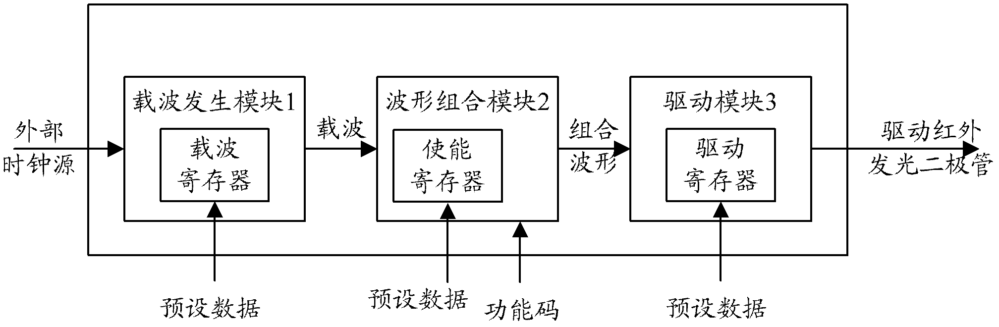
[0029] see Figure 1 to Figure 4 As shown, the circuit structure for controlling infrared remote control emission, wherein the circuit structure includes:

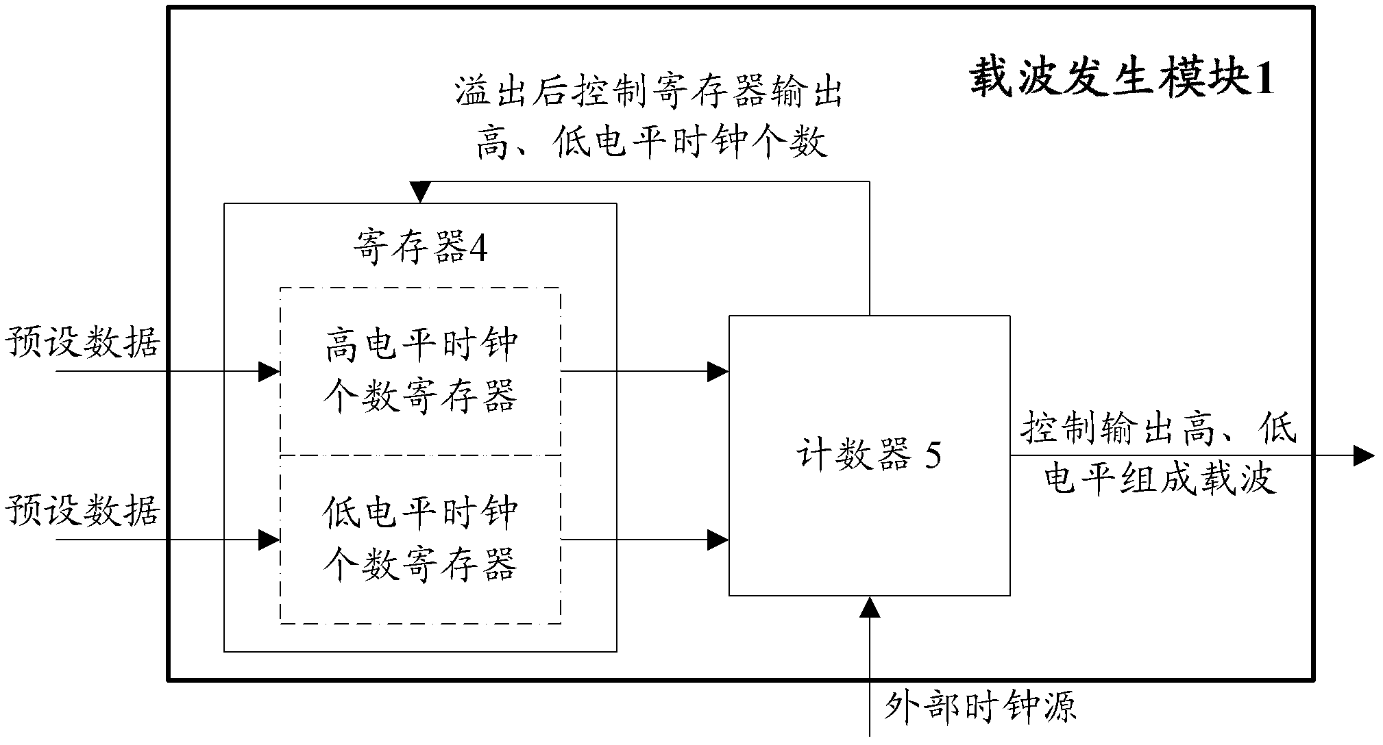
[0030] (1) The carrier generation module controls the high and low level length of the carrier according to the preset value; including:

[0031] ●Register, which saves the high and low level length data information of the preset carrier; the register includes a high level clock number register and a low level clock number register;

[0032] The counter is connected to the register and is used to control the number of high and low level clocks of the carrier according to the preset value;

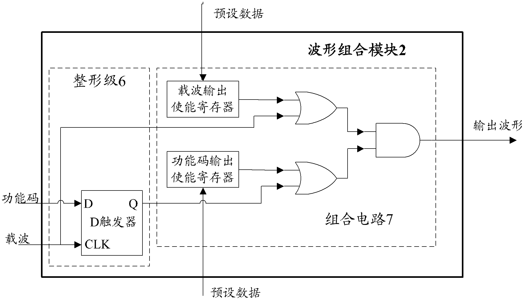
[0033] (2) waveform combination module, connected with the carrier generation module, used to combine carrier and function code, and select only transmitting carrier or only transmitting function cod...


PUM


Abstract

The invention relates to a circuit structure for controlling infrared remote control emission. The circuit structure comprises a carrier wave generation module for controlling high and low level length of the carrier wave according to a preset value, a waveform combination module which is connected with the carrier wave generation module and used for combining the carrier wave and a function code and selecting to only emit the carrier wave or only emit the function code according to a user operation, a driving module which is connected with the waveform combination module and used for selecting a driving mode and driving capacity. The circuit structure for controlling infrared remote control emission by employing the structure saves system overhead, is convenient for testing and debugging in large-scale production. An original circuit board continues to use an externally installed driving mode, and a novel circuit board employs an internally installed driving mode. The driving capacity can be selected in the internally installed driving mode, so that the internally installed driving mode is more flexible. At the same time, the driving capacity can be selected according to actual requirements, and different driving capacities can be selected according to emission distance so as to reduce power consumption, thereby prolonging a service life of the battery and obviously reducing cost of a whole machine. Work performance is stable and reliable, and an application range is relatively wide.

Description

technical field [0001] The invention relates to the field of infrared remote control, in particular to the technical field of infrared remote control emission control, and specifically refers to a circuit structure for controlling infrared remote control emission. Background technique [0002] Infrared remote control technology has developed rapidly in recent years, especially in the field of home appliances such as color TVs, DVDs, air conditioners, etc., and is also widely used in other electronic fields. With the widespread application of remote controls in people's lives, there are higher requirements for remote control manufacturers' development time, overall machine cost, and power consumption indicators. [0003] In the prior art, traditional infrared remote control transmitting circuits generally use external triodes to drive infrared light emitting diodes. The procurement cost of transistors and current limiting resistors is unavoidable. [0004] In the infrared r...

Claims


Application Information

Patent Timeline
Patent Type & Authority Applications(China)
IPC IPC(8): G08C23/04
Inventor 高庆陆健王效赵海
Owner CRM ICBG (WUXI) CO LTD
Why Eureka
Try Eureka