Cooling structure and cooling method of photovoltaic inverter device

A photovoltaic inverter and cooling structure technology, applied in photovoltaic power generation, conversion of irreversible DC power input to AC power output, cooling/ventilation/heating transformation, etc., can solve insufficient heat dissipation, inverter device failure, accidents, etc. question

Inactive Publication Date: 2015-08-05
上海伊阿宋文化科技有限公司 +1
View PDF5 Cites 1 Cited by
  • Summary
  • Abstract
  • Description
  • Claims
  • Application Information

AI Technical Summary

Problems solved by technology

The cooling structure is a low-cost, multi-air channel cooling structure mainly based on natural heat dissipation, and an auxiliary forced air cooling device is added, which can solve the problem of insufficient heat dissipation and cooling caused by the traditional radiator, which leads to failure of the inverter due to overheating and equipment accidents, or reduce the life of the inverter device, etc.

Method used


Image

  • Cooling structure and cooling method of photovoltaic inverter device
  • Cooling structure and cooling method of photovoltaic inverter device
  • Cooling structure and cooling method of photovoltaic inverter device

Examples


Embodiment Construction

[0028] In order to make the technical means, creative features, goals and effects achieved by the present invention easy to understand, the present invention will be further described below in conjunction with specific illustrations.

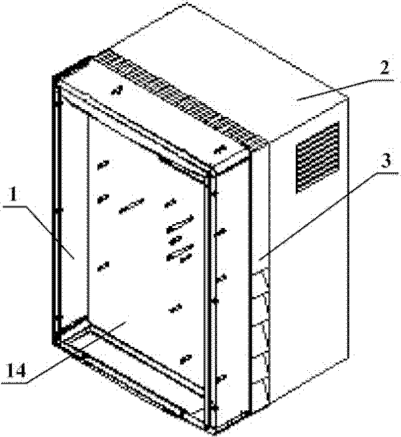
[0029] see figure 1 , the chassis of the entire photovoltaic inverter device is composed of a front cabin 1 , a rear cabin 2 and a cooling cabin 3 . Wherein the middle of the cooling cabin runs through the air flow channel and the front cabin bottom plate 14 and the rear cabin 2 are integrated, and provide heat dissipation for the inverter device as a whole.

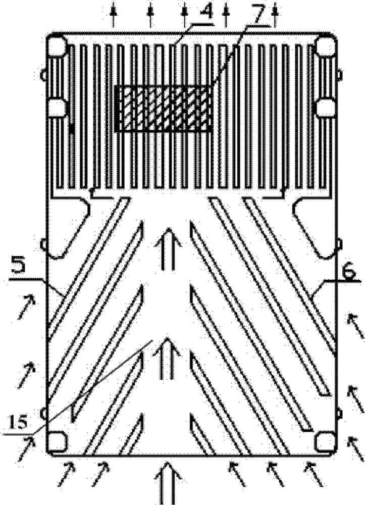
[0030] The cooling structure of the photovoltaic inverter device provided by the present invention mainly includes a heat dissipation main air duct and a heat dissipation auxiliary air duct.

[0031] see figure 2 , the main heat dissipation air channel is located in the cooling cabin 3, specifically the middle through channel between the front cabin 1 and the rear cabin 2 of the inverte...


PUM


Abstract

The invention discloses a cooling structure and a cooking method of a photovoltaic (PV) inverter. The cooling structure of the PV inverter mainly comprises convection air inlet channels on two sides and at the bottom of a cooling chamber, and a heat dissipation air channel of a rear chamber. A main air channel is a middle passing-through air flow channel located between a front chamber and the rear chamber of the inverter. An auxiliary air channel is located in the rear chamber of the inverter, and auxiliary heat dissipation air channels are formed from an air inlet to an air outlet and from the air inlet to an air exhaust groove of the cooling chamber. In order to meet the cooling requirement under a high-temperature environment, a fan is used for carrying out forced air cooling heat dissipation. Through the multiple air channel cooling method, the problems that when a traditional radiator method is used, heat cannot be dissipated sufficiently, and the temperature cannot be lowered sufficiently, so that the inverter is overheated to cause a failure and equipment accidents, or the service life of the inverter is shortened, and the like can be solved.

Description

technical field [0001] The invention relates to the photovoltaic grid-connected inverter device technology, in particular to a cooling structure of the photovoltaic inverter device and a self-cooling method. Background technique [0002] Among new energy sources, solar energy, as an efficient and pollution-free renewable energy with the most development prospects, has become an important part of today's energy supply, and it is a development trend that solar energy with photovoltaic effect has become the mainstream energy source of renewable energy. [0003] Photovoltaic inverter is the key equipment in solar photovoltaic power generation system. To measure the quality of a photovoltaic inverter, in addition to some important technical indicators, it is an important technology for inverter progress to minimize the temperature of inverter heating elements under specific inverter loss and operating heating conditions . [0004] At present, the difficulties of photovoltaic in...

Claims


Application Information

Patent Timeline
Patent Type & Authority Patents(China)
IPC IPC(8): H02M7/42H05K7/20
CPCY02E10/56
Inventor 章伟康朋泰彧褚君浩
Owner 上海伊阿宋文化科技有限公司
Why Eureka
Try Eureka