floor-standing indoor unit

An indoor unit and floor-standing technology, applied in the field of floor-standing indoor units, can solve the problems of insufficient air supply to the rear heat exchanger and reduced heat exchange efficiency of the heat exchanger, so as to suppress insufficient supply, reduce heat exchange efficiency, Effect of reducing ventilation resistance

Inactive Publication Date: 2016-05-11
DAIKIN IND LTD
View PDF5 Cites 0 Cited by
  • Summary
  • Abstract
  • Description
  • Claims
  • Application Information

AI Technical Summary

Problems solved by technology

Therefore, there is a problem that sufficient air cannot be supplied to the rear heat exchanger, and the heat exchange efficiency of the heat exchanger is lowered.

Method used


Image

  • floor-standing indoor unit
  • floor-standing indoor unit
  • floor-standing indoor unit

Examples


Embodiment Construction

[0044] Next, the air conditioner 100 provided with the floor-standing indoor unit 1 of the embodiment of the present invention will be described.

[0045]

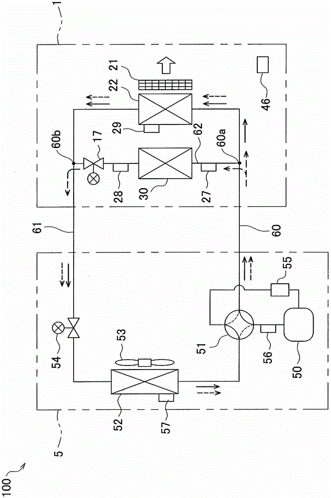
[0046] Such as figure 1 As shown, the air conditioner 100 of the present embodiment includes a floor-standing indoor unit 1 (hereinafter, simply referred to as “indoor unit”) installed indoors, and an outdoor unit 5 installed outdoors. The indoor unit 1 includes an indoor heat exchanger 22, a cross-flow fan 21 arranged near the indoor heat exchanger 22, a radiation panel 30, an indoor electric valve 17, and an indoor temperature sensor 46 for detecting indoor air temperature. In addition, the outdoor unit 5 includes a compressor 50, a four-way switching valve 51, an outdoor heat exchanger 52, an outdoor fan 53 arranged near the outdoor heat exchanger 52, and an outdoor electric valve 54.

[0047] The refrigerant circuit 60 has an annular main flow path 61 that connects the indoor heat exchanger 22, the compressor 50, the four-w...


PUM


Abstract

Prevent heat exchange efficiency from decreasing. The indoor heat exchanger (22) housed in the casing (10) includes: a front heat exchanger (22a) arranged to face the back of the front panel (4); and a back heat exchanger (22b) along with It is inclined upward as it approaches from the vicinity of the lower end of the front heat exchanger (22a) to the back. An upper filter (16a) and a lower filter (16b) are provided in the flow path from the main suction port (10a) provided in front of the lower end of the casing (10) to the front heat exchanger (22a). And at least a part of the part below the front heat exchanger (22a) of the lower filter (16b) is curved so that it may protrude forward.

Description

Technical field [0001] The present invention relates to a floor-standing indoor unit having a substantially V-shaped heat exchanger having a front heat exchanger and a back heat exchanger. Background technique [0002] As a conventional floor-standing indoor unit, there is known a floor-standing indoor unit that sucks air in the vicinity of the floor from an inlet provided in front of the lower end of the housing and blows it out from a blower outlet provided at the upper end of the housing ( For example, refer to Patent Document 1). The air sucked in from the suction port is supplied to the heat exchanger housed in the housing, and is heated by heat exchange with the refrigerant flowing in the heat exchanger. In addition, the heated air is blown out from the blower outlet. [0003] Prior art literature [0004] Patent literature [0005] Patent Document 1: Japanese Unexamined Publication No. 63-185023 Summary of the invention [0006] The problem to be solved by the invention [00...

Claims


Application Information

Patent Timeline
Patent Type & Authority Patents(China)
IPC IPC(8): F24F13/28F24F13/30F24F1/0073
CPCF24F13/30F24F5/0089F24F13/28F24F1/005F24F1/0073
Inventor 滨健郎
Owner DAIKIN IND LTD
Why Eureka
Try Eureka