Production method of rare earth magnet

A technology of rare earth magnets and rare earth elements, which is applied in the fields of magnetic objects, inductance/transformer/magnet manufacturing, magnetic materials, etc., and can solve unknown problems

Active Publication Date: 2013-07-03
TOYOTA JIDOSHA KK +3
View PDF8 Cites 9 Cited by
  • Summary
  • Abstract
  • Description
  • Claims
  • Application Information

AI Technical Summary

Problems solved by technology

[0004] However, it is unknown whether the above effect

Method used


Image

  • Production method of rare earth magnet
  • Production method of rare earth magnet
  • Production method of rare earth magnet

Examples


no. 1 approach 》

[0047]

[0048] A representative example of the composition of a rare earth magnet is represented by the following composition formula:

[0049] R 1 v Fe w co x B y m 1 z

[0050] R 1 : one or more rare earth elements including Y,

[0051] m 1 : at least one of Ga, Zn, Si, Al, Nb, Zr, Ni, Cu, Cr, Hf, Mo, P, C, Mg and V,

[0052] 13≤v≤20,

[0053] w=100-v-x-y-z,

[0054] 0≤x≤30,

[0055] 4≤y≤20,

[0056] 0≤z≤3.

[0057] Preferably, in the composition formula R 1 v Fe w co x B y m 1 z in, R 1 The amount v of (one or more rare earth elements including Y) is 13≦v≦17, and the amount y of B is 5≦y≦16.

[0058] Another representative example of the composition of the rare earth magnet is represented by the following composition formula, and consists of the main phase ((R 2 R 3 ) 2 (FeCo) 14 B) and grain boundary phase ((R 2 R 3 )(FeCo) 4 B 4 Phase and R 2 R 3 phase) composition:

[0059] R 2 a R 3 b Fe c co d B e m 2 f

[0060] R 2 : one o...

no. 2 approach 》

[0109]

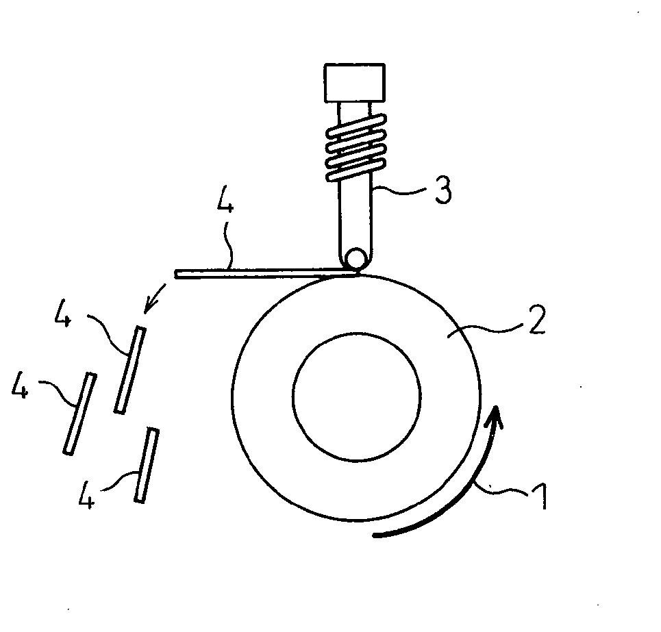
[0110] The film with the rare earth magnet composition is deposited on the substrate by any type of method such as chemical vapor deposition (CVD) and physical vapor deposition (PVD). The thickness of the film may be 0.50 μm or more, 1.00 μm or more, 2.00 μm or more, or 3.00 μm or more. In addition, the thickness of the film may be 1000 μm or less, 100 μm or less, 50 μm or less, or 10 μm or less.

[0111]

[0112] After the film is deposited, heat treatment under pressure is applied, which is a characteristic feature of the present invention. To this end, the difference in the thermal expansion coefficients of the substrate and the film deposited thereon can be exploited.

[0113] The pressure applied to the film during the pressurized heat treatment may be 1 MPa or more, 5 MPa or more, 10 MPa or more, 50 MPa or more, or 100 MPa or more, and may be 300 MPa or less, 400 MPa or less, or 500 MPa or less. The pressure heat treatment time may be 1 minute or more, 3 m...

Embodiment

[0116] [Reference Example 1-4]

[0117] It was confirmed in Reference Examples 1-4 below that rare earth magnets with improved magnetic coercive force were obtained in the method of the present invention for producing rare earth magnets compared to conventional methods not involving heat treatment, even when heat treatment was not accompanied by the addition of The same is true when pressing.

[0118] [Reference Example 1]

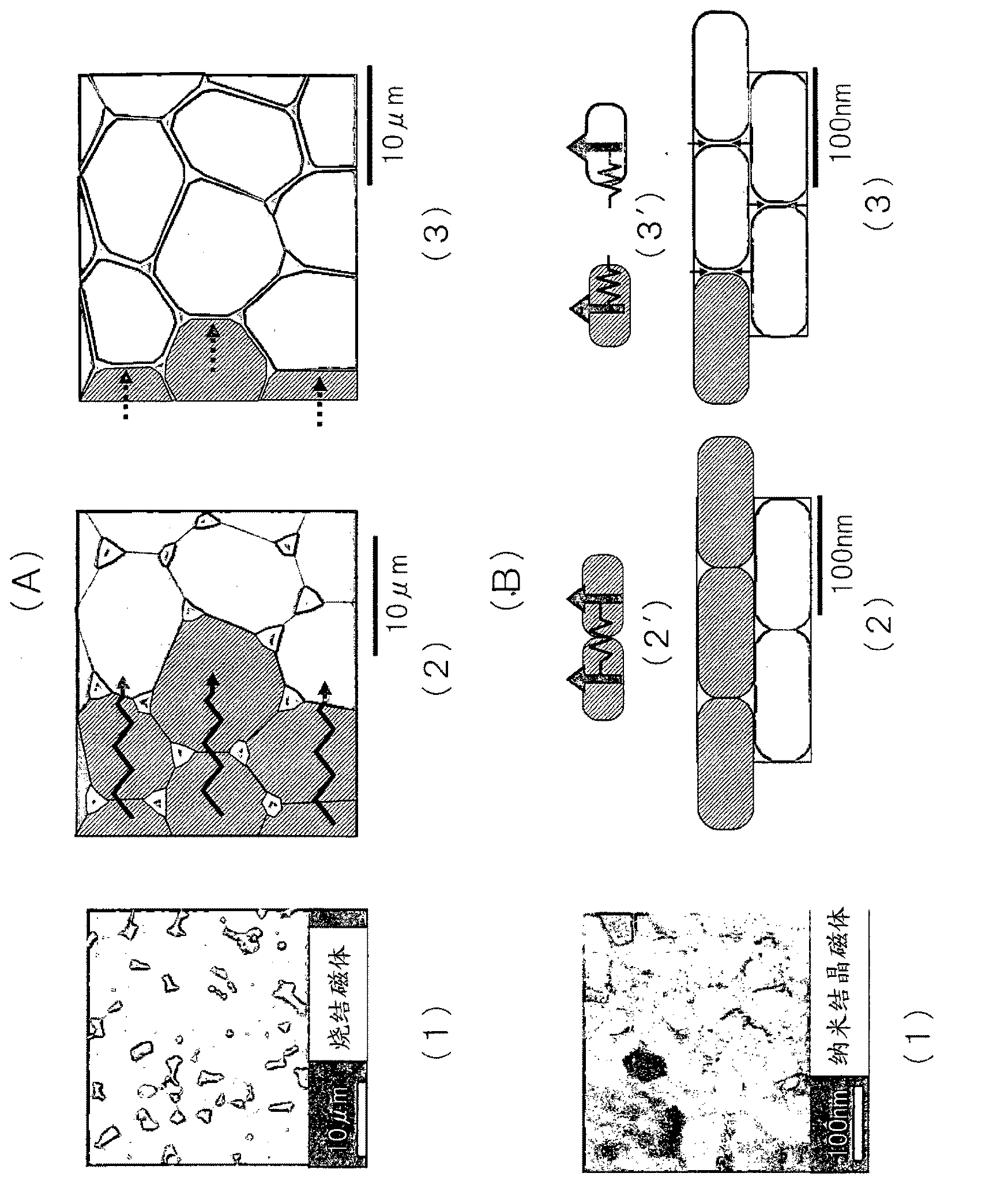
[0119] The preparation composition is Nd 15 Fe 77 B 7 Ga 1 Nanocrystalline rare earth magnets and compositions containing Al and Cu, that is, Nd 15 Fe 77 B 6.8 Ga 0.5 al 0.5 Cu 0.2 nanocrystalline rare earth magnets. The final structure is composed of the main phase: Nd 2 Fe 14 B 1 Phase and grain boundary phase: Nd-rich phase (Nd or Nd oxide) or Nd 1 Fe 4 B 4 Phase composition of nanocrystalline structure. Ga is enriched in the grain boundary phase to prevent movement of grain boundaries and suppress coarsening of crystal grains. Both A...


PUM

PropertyMeasurementUnit
Thicknessaaaaaaaaaa
Melting pointaaaaaaaaaa
Magnetic coercive forceaaaaaaaaaa

Abstract

The method of the present invention produces a rare earth magnet, which is represented by a neodymium magnet (Nd2Fe14B) and neodymium magnet films with applications in micro-systems, by using a heat treatment method capable of enhancing the magnetic characteristics, particularly the magnetic coercive force. A method for producing a rare earth magnet, comprising: (a)quenching a molten metal having a rare earth magnet composition to form quenched flakes of nanocrystalline structure; sintering the quenched flakes; subjecting the sintered body obtained to an orientation treatment; and applying a heat treatment with pressurization at a temperature sufficiently high to enable diffusion or fluidization of a grain boundary phase and at the same time, low enough to prevent coarsening of the crystal grains. (b) thick films deposited on a substrate, applying an annealing to crystallize with pressurization at a temperature sufficiently high to enable diffusion or fluidization of a grain boundary phase and, at the same time, low enough to prevent coarsening of the crystal grains. Preferably, an element capable of lowering the temperature at which the grain boundary phase can be diffused or fluidized, is added to the rare earth magnet composition.

Description

technical field [0001] The present invention relates to a preparation method of a rare-earth magnet, which is generally represented by neodymium magnets and neodymium magnet films applied to MEMS (micro-electromechanical systems). More specifically, the present invention relates to a method of preparing a rare earth magnet having a structure composed of nano-sized grains. Background technique [0002] Rare earth magnets, neodymium magnets (Nd 2 Fe 14 B) and neodymium magnet films are represented as very strong permanent magnets with high magnetic flux density for a variety of applications. To further increase the magnetic coercive force, the grain size is being reduced to the nanoscale (tens to hundreds of nm). [0003] In a typical sintered magnet (grain size: several μm or more), it is well known that heat treatment is applied after sintering to increase the magnetic coercive force. For example, it is confirmed in Patent Documents 1 and 2 that when aging heat treatment...

Claims


Application Information

Patent Timeline
IPC IPC(8): H01F41/02H01F41/32
CPCH01F1/0577H01F10/126H01F41/0273H01F41/32C22C38/002C22C38/005C22C38/06C22C38/16B22F2003/248B22F2998/00B22F2998/10B22F2999/00C22C2202/02H01F1/0576B22F3/105B22F1/07B22F1/068B22F9/08B22F3/10B22F3/24H01F1/01H01F41/00H01F41/005
Inventor 佐久间纪次岸本秀史加藤晃庄司哲也多米尼克·吉沃尔诺拉·登普西托马斯·格奥尔格·伍德科克奥利弗·古特弗莱施吉诺·赫尔卡克托马斯·施雷弗
Owner TOYOTA JIDOSHA KK
Why Eureka
Try Eureka