Electric and optical cable metering and printing device
A printing and optical cable technology, which is applied in the field of cable and optical cable meter printing device, can solve the problems of inconvenient operation and complex structure, and achieve the effects of simple structure, reduced production cost, and saved consumption
- Summary
- Abstract
- Description
- Claims
- Application Information
AI Technical Summary
Problems solved by technology
Method used
Image

Examples
Embodiment Construction
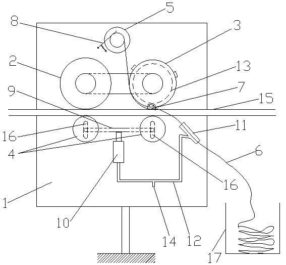
[0018] Such as figure 1 As shown, a cable and optical cable meter printing device includes a base plate 1 perpendicular to the ground, the upper half of the base plate 1 is equipped with a friction transmission metering wheel 2, a printing wheel 3 and a printing tape reel 5, the base plate 1 Two streamers 4 are installed in the lower half, and the cables or optical cables 15 are sandwiched between the friction transmission metering wheel 2 and one streamer 4, printing wheel 3 and another streamer 4 respectively, and are coiled on the The printing tape 6 on the printing tape reel 5 bypasses the edge of the printing wheel 3, and is passed between the printing wheel 3 and the electric or optical cable 15, and the friction-driven metering wheel 2 passes between the electric or optical cable 15. The contact friction between them generates rotation, and then the printing wheel 3 is driven to rotate through the belt drive. The printing wheel 3 is equipped with several printing blocks...
PUM
 Abstract
Description
Claims
Application Information
 - R&D
- Intellectual Property
- Life Sciences
- Materials
- Tech Scout
- Unparalleled Data Quality
- Higher Quality Content
- 60% Fewer Hallucinations
Browse by: Latest US Patents, China's latest patents, Technical Efficacy Thesaurus, Application Domain, Technology Topic, Popular Technical Reports.
© 2025 PatSnap. All rights reserved.Legal|Privacy policy|Modern Slavery Act Transparency Statement|Sitemap|About US| Contact US: help@patsnap.com