Autocrane hoisting manner and autocrane rubber suspension system
A technology for truck cranes and suspension systems, applied in cranes, suspensions, elastic suspensions, etc., can solve problems such as affecting the performance of rubber springs, failure of suspension systems, and breaking rubber springs, so as to improve reliability and improve tension. The effect of the extension force case
- Summary
- Abstract
- Description
- Claims
- Application Information
AI Technical Summary
Problems solved by technology
Method used
Image
Examples
Embodiment 1
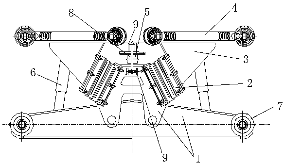
[0041]Embodiment 1: A kind of hoisting method of a truck crane, a limit belt is set between the saddle of the rubber suspension system of the truck crane and the equalizing beam or between the equalizing beam and the frame of the truck crane, and the vehicle is completed with the help of the limit belt. Lifting of the crane; the spacer band is subjected to the downward pull of the unsprung mass during hoisting, and the spacer band changes from a relaxed state to a stretched state; when the lifting is completed, the spacer band changes from a stretched state to a relaxed state, The tires of a truck crane bear the downward pull of the unsprung mass. The lifting method at least includes the following steps: 1) When lifting, put down the hydraulic support legs and leave the tires off the ground. At this time, the rubber suspension system of the truck crane is supported by the spring through the limit belt arranged on the rubber suspension system. The downward pulling force of the ...
Embodiment 2
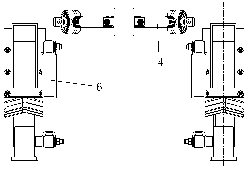
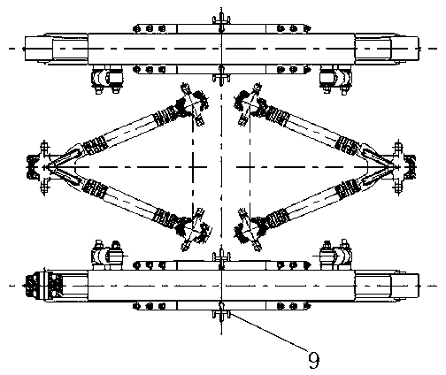
[0046] Implementation 2: If Figures 9 to 10 As shown, compared with Embodiment 1, the only difference is that the assembly lifting lug 9 is only set on the equalizing beam 1, and the limit belt 8 is connected by the assembly lifting lug 9 of the equalizing beam 1 and the lifting lug on the vehicle frame. For the equalizing beam 1 and the vehicle frame, the length 13 of the limiting band 8 is 500mm. The mounting lugs 9 are arranged on the inner and outer surfaces of the equalizing beam 1 . The number of the mounting lugs 9 is four. The material of the position-limiting band 8 is nylon material. The elastic rubber layer 11 and the metal spacer 10 are 4 and 5 layers respectively. The distance 12 between the lowermost end of the limiting block 5 and the uppermost end of the equalizing beam 1 is 140mm. The thrust rod 4 is a straight thrust rod with two horizontal and two vertical arrangements.
Embodiment 3
[0047] Implementation 3: If Figures 11 to 14 As shown, compared with Embodiment 1, the only difference is that the assembly lifting lug 9 is only set on the equalizing beam 1, and the limit belt 8 is connected by the assembly lifting lug 9 of the equalizing beam 1 and the lifting lug on the vehicle frame. For the equalizing beam 1 and the vehicle frame, the length 13 of the limiting band 8 is 800 mm, the assembly lifting lug 9 is arranged on the outer surface of the equalizing beam 1 , and the number of the assembly lifting lug 9 is two. The material of the limiting band 8 is polyester fiber material. The distance 12 between the lowermost end of the limiting block 5 and the uppermost end of the equalizing beam 1 is 70 mm. The thrust rod 4 is a V-shaped straight thrust rod.
[0048] In summary, through the technical solution of the present invention, during the hoisting process, the limiting belt is in a tight state and bears most of the tensile load, so as to ensure that th...
PUM
 Abstract
Description
Claims
Application Information
 - R&D
- Intellectual Property
- Life Sciences
- Materials
- Tech Scout
- Unparalleled Data Quality
- Higher Quality Content
- 60% Fewer Hallucinations
Browse by: Latest US Patents, China's latest patents, Technical Efficacy Thesaurus, Application Domain, Technology Topic, Popular Technical Reports.
© 2025 PatSnap. All rights reserved.Legal|Privacy policy|Modern Slavery Act Transparency Statement|Sitemap|About US| Contact US: help@patsnap.com


