High-load retarder with welding type piston

A deceleration jack and high-load technology, which is applied in the direction of railway car body parts, track brakes, transportation and packaging, etc., can solve the problems of inability to judge the speed in different stages, and the large flow area of ​​the speed judgment, so as to reduce the production cost and work The effect of plumping and reducing the difficulty of processing

Inactive Publication Date: 2013-07-10
哈尔滨铁路减速顶调速研究有限公司
View PDF7 Cites 3 Cited by
  • Summary
  • Abstract
  • Description
  • Claims
  • Application Information

AI Technical Summary

Problems solved by technology

[0004] The purpose of the present invention is to provide a welded piston high-load deceleration jack to solve the problem that the existing high-load deceleration jack has a large speed judging flow area and cannot perform speed judgment and classification.

Method used


Image

  • High-load retarder with welding type piston
  • High-load retarder with welding type piston
  • High-load retarder with welding type piston

Examples


specific Embodiment approach 1

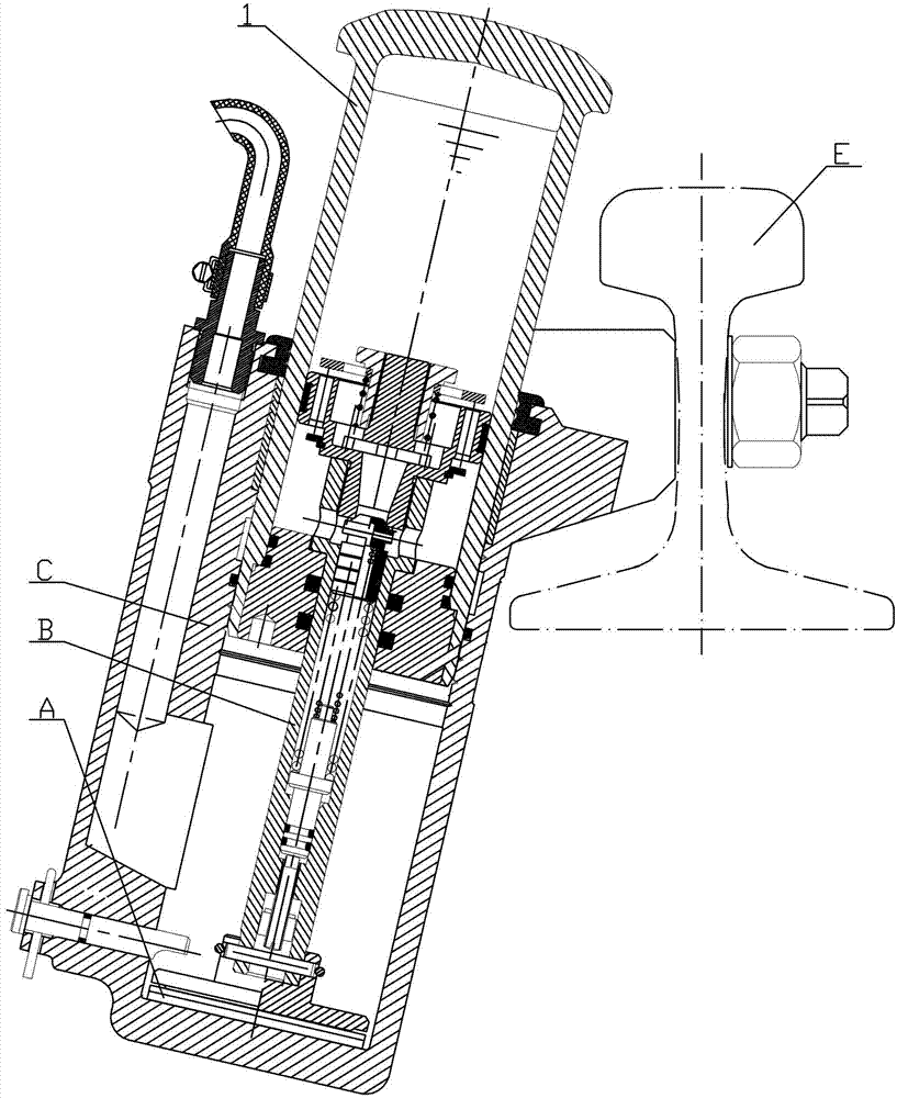
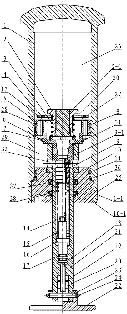
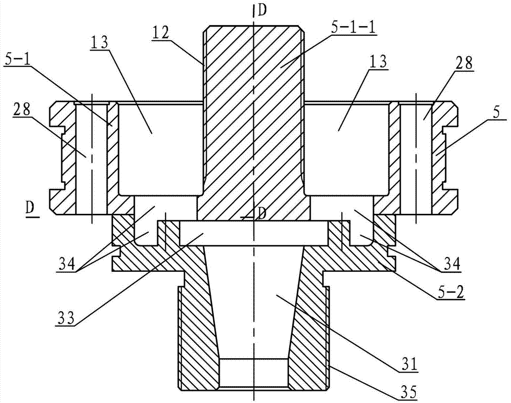
[0013] Specific implementation mode one: combine Figure 1 to Figure 6 Describe this embodiment. This embodiment includes a sliding cylinder assembly B and a housing C. The sliding cylinder assembly B includes a sliding cylinder 1, a speed valve seat 2, a speed valve spring 3, a speed valve plate 4, a piston 5, and a return stroke Valve plate 6, retaining ring 7, support ring 8, pressure valve stem 9, sealing cover 10, pressure valve inner spring 14, pressure valve outer spring 15, spring seat 16, fifth O-ring 17, pressure regulating screw 18, Washer 19, lock cap 20, piston rod 21, anti-shock seat 22, connecting pin 23, snap ring 24 and pin 25, the piston rod 21 is equipped with lock cap 20, washer 19, pressure regulating screw 18, The fifth O-shaped sealing ring 17, spring seat 16, pressure valve outer spring 15, pressure valve inner spring 14 and pressure valve stem 9, the piston 5 is composed of an upper piston 5-1 and a lower piston 5-2, and the upper piston 5-1 A second ...

specific Embodiment approach 2

[0014] Specific implementation mode two: combination figure 2 Referring to this embodiment, the sliding cylinder assembly B of this embodiment further includes a first O-ring 11 , and the first O-ring 11 is disposed between the sealing cover 10 and the sliding cylinder 1 . The first O-ring 11 is used to increase the sealing performance between the sealing cover 10 and the sliding cylinder 1 . Other components and connections are the same as those in the first embodiment.

specific Embodiment approach 3

[0015] Specific implementation mode three: combination figure 2 Describe this embodiment, the sliding oil cylinder assembly B of this embodiment also includes a second O-ring seal 36, and the second O-ring sealing ring 36 is arranged below the first O-ring sealing ring 11 and is located between the sealing cover 10 and the sliding oil cylinder. between 1. The second O-ring 36 enables better sealing between the sealing cover 10 and the sliding cylinder 1 . Other components and connections are the same as those in the second embodiment.


PUM


Abstract

A high-load retarder with a welding type piston relates to a retarder and aims at solving the problem that the existing high-load retarder is large in speed judgment overflow area and cannot conduct speed judgment gear selection. A second overflow channel is arranged on an upper piston, a plurality of first overflow channels parallel to the second overflow channel are arranged on the lateral wall of the upper piston along a circle, a groove is arranged on the upper end face of a lower piston, a Y-shaped channel is arranged at the center position of the lower piston, and the lower end face of the upper piston and the upper end face of the lower piston are mutually welded. A vertical overflow hole is arranged on the connection face of the upper piston and the lower piston, a sealing cover is connected with the lower end of a sliding oil cylinder in sealing mode, a valve plate overflow hole is arranged on a speed valve plate, a speed valve spring is arranged in the second overflow channel, a transverse oil through hole is arranged on a piston rod at the lower end of each piston, the overflow area of the upper end of the Y-shaped channel is smaller than the overflow area of the vertical overflow hole, and the overflow area of the vertical overflow hole is smaller than the overflow area of the second overflow channel. The high-load retarder is used for railway deceleration.

Description

technical field [0001] The invention relates to a deceleration top, in particular to a welded piston high-load deceleration top. Background technique [0002] With the development requirements of high-speed and heavy-duty railways at home and abroad, the speed-regulating equipment of high-load series deceleration jacks has been widely promoted and applied. The piston is one of the important components of the high-load retarder, which directly determines the braking performance of the high-load retarder. [0003] The Chinese patent number is ZL200420063146.2, and the patent of invention issued on September 28, 2005 discloses a "high-load deceleration top". Although the deceleration top has high body strength, good overall guidance, high critical speed accuracy, The number of cloth tops is small, the occupied line is short, the load performance is high, and the safety performance is good. The piston and the piston rod of the deceleration top have an integrated structure. Alth...

Claims


Application Information

Patent Timeline
Patent Type & Authority Applications(China)
IPC IPC(8): B61K7/02
Inventor 邱满根刘孝威胡东东王潜王旭高福生刘丽娜陈峰王晓蕾郭爽
Owner 哈尔滨铁路减速顶调速研究有限公司
Why Eureka
Try Eureka