Elevator hydraulic buffer resetting performance dynamic measuring method and tester adopted by method

A technology of hydraulic buffer and measurement method, applied in elevators, transportation and packaging, etc., can solve problems such as inapplicability of elevator inspection rules, failure to fully reflect the dynamic process of elevator buffers, and errors in measurement results, etc. Easy to install and easy to carry

Active Publication Date: 2015-07-15
SHUNDE BRANCH GUANGDONG INST OF SPECIAL EQUIP INSPECTION & RES
View PDF5 Cites 0 Cited by
  • Summary
  • Abstract
  • Description
  • Claims
  • Application Information

AI Technical Summary

Problems solved by technology

Although testers for detecting the reset time of elevator buffers have been developed in China, the compressed images of the buffers depicted by these testers start from the time when the car touches the buffers, and the moment when the car is lifted cannot be truly confirmed, so Existing testers are not suitable for the newly implemented elevator inspection rules
At the same time, the originally developed tester failed to automatically identify the situation where the elevator buffer was kept at the maximum compression state due to a jamming fault, resulting in errors in the measurement results
Moreover, the commonly developed elevator buffer reset time testers are basically aimed at the test item itself, that is to say, the measured data is the reset time, and does not fully reflect the entire dynamic process of elevator buffer reset.
At this stage, there is no tester that can monitor the entire action and reset process of the elevator buffer, and provide analysis data for the cause of the buffer's action jamming or reset timeout.

Method used


Image

  • Elevator hydraulic buffer resetting performance dynamic measuring method and tester adopted by method
  • Elevator hydraulic buffer resetting performance dynamic measuring method and tester adopted by method
  • Elevator hydraulic buffer resetting performance dynamic measuring method and tester adopted by method

Examples


Embodiment

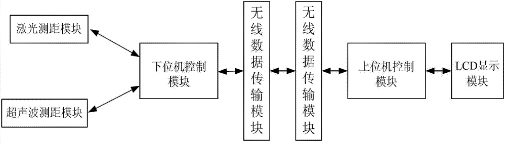
[0043] In this embodiment, the laser ranging module is adopted as a laser rangefinder whose model is LRFS (HYKOL)-0040-1 / 2, the ultrasonic ranging module is an ultrasonic rangefinder whose model is KS103, and the wireless data module whose model is APC220-43 The transfer module is described below.

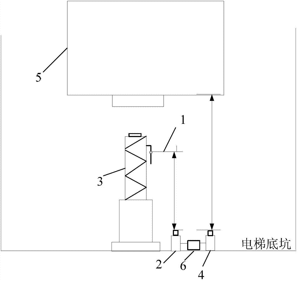
[0044] The module structure diagram of the elevator hydraulic buffer reset performance dynamic tester of the present invention is as follows figure 1 As shown, the tester includes a baffle, a laser distance measuring module for measuring the distance change between the baffle and the elevator pit floor, and an ultrasonic distance measuring module for measuring the distance change between the elevator car and the elevator pit , used to save data in real time, receive feedback signals from the laser ranging module and ultrasonic ranging module, and control the lower computer control module of the laser ranging module and ultrasonic ranging module, used to receive feedback information...


PUM


Abstract

The invention provides an elevator hydraulic buffer resetting performance dynamic measuring method. The measuring method comprises the following steps of first, measuring an initial distance between a blocking plate and the ground of an elevator bottom pit; second, measuring a distance between the blocking plate and the ground of the elevator bottom pit; third, judging whether an elevator car goes down or not and whether the elevator car is contacted with an elevator buffer; fourth, measuring a distance between the elevator car and the elevator bottom pit; fifth, judging whether the elevator car goes up or not; sixth, judging whether the elevator buffer finishes resetting; and seventh, processing data to obtain resetting time of the elevator buffer and analyzing the resetting performance of the elevator buffer. The measuring method can quickly and accurately measure the resetting time of the buffer, ensures the buffer to meet the safety requirement, and accordingly improves the measuring accuracy and the work efficiency of inspectors. The invention further provides a tester adopted by the method. The tester is simple in installation and meets the requirements of newly adopted elevator inspection procedures.

Description

technical field [0001] The invention relates to the technical field of elevator detection, in particular to a method for measuring the dynamic reset performance of an elevator hydraulic buffer and a tester thereof. Background technique [0002] The detection of the reset performance of the elevator buffer is the detection of the entire dynamic process of the reset after the buffer is compressed. Among them, the detection of the reset time of the elevator buffer is a mandatory inspection item in the elevator inspection rules and elevator manufacturing and installation standards; And in the elevator supervision and inspection process, the detection of the elevator buffer reset time is one of the basis for judging the safety status of the elevator, and the accuracy of measuring the elevator reset time can directly affect the judgment of whether the elevator is safe or not. [0003] When inspecting the reset time of the elevator buffer, considering the personal safety of the ins...

Claims


Application Information

Patent Timeline
Patent Type & Authority Patents(China)
IPC IPC(8): B66B5/00
Inventor 曾健生李越胜陈永煊林云莉吴思勉
Owner SHUNDE BRANCH GUANGDONG INST OF SPECIAL EQUIP INSPECTION & RES
Why Eureka
Try Eureka