A near-infrared fluorescent emission material excited by broadband ultraviolet-visible light and its preparation method and application
A fluorescent emission and visible light technology, which is applied in luminescent materials, photovoltaic power generation, chemical instruments and methods, etc., can solve the problems of not being able to use sunlight at a high level and limit the improvement of solar cell efficiency, and achieve high yield and easy long-term The effect of simple preservation and preparation process
- Summary
- Abstract
- Description
- Claims
- Application Information
AI Technical Summary
Problems solved by technology
Method used
Image
Examples
Embodiment 2
[0030] Weigh 0.5589g (2.475mmol) Y 2 o 3 , 0.7112g (6.975mmol) Al 2 o 3 , 1.4839 g (24 mmol) H 3 BO 3 , 0.1401g (1.05mmol) Cr(NO 3 ) 3 9H 2 O and 0.0099g (0.025mmol) Yb 2 o 3 Place in a fume hood and mix, add 50% of the total weight of the mixture in absolute ethanol, grind and mix; dry in a blast drying oven at 80°C; collect the dried mixture powder into a corundum crucible, Put it into a muffle furnace, heat up to 1200°C at a heating rate of 2°C / min, sinter for 5 hours, cool to room temperature, and grind a little to get the target product.
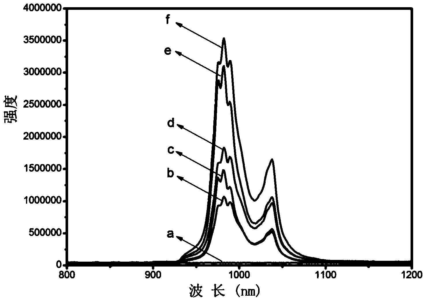
[0031] The fluorescent material prepared in this example is excited at 420nm to obtain a fluorescence emission spectrum, see for details figure 1 (b) spectrum in (b), given by figure 1 Visible, infrared emission main peak wavelength: 983nm, fluorescence intensity of target product (arbitrary unit): 1069236.
Embodiment 3
[0033] Y in Example 2 2 o 3 The amount of addition becomes 0.5476g (2.425mmol), Yb 2 o 3The addition amount of was changed to 0.0296g (0.075mmol), and other conditions were unchanged, and the target product was obtained.
[0034] The fluorescent material prepared in this example is excited at 420nm to obtain a fluorescence emission spectrum, see for details figure 1 (d) spectrum in (d), given by figure 1 Visible, infrared emission main peak wavelength: 983nm, fluorescence intensity of target product (arbitrary unit): 1832976.
Embodiment 4
[0036] Y in Example 2 2 o 3 The amount of addition becomes 0.5250g (2.325mmol), Yb 2 o 3 The addition amount of was changed to 0.0690g (0.175mmol), and other conditions were unchanged, and the target product was obtained.
[0037] The fluorescent material prepared in this example is excited at 420nm to obtain a fluorescence emission spectrum, see for details figure 1 (f) spectrum in , given by figure 1 Visible, infrared emission main peak wavelength: 983nm, fluorescence intensity of target product (arbitrary unit): 3538700.
[0038] Figure 4 It is a fluorescence absorption spectrum diagram of the fluorescent material prepared in this embodiment, and it can be seen from the figure that the fluorescent material has a strong fluorescence intensity at an excitation wavelength between 350nm and 650nm.
[0039] Figure 5 It is the fluorescence emission spectrum diagram of the fluorescent material prepared in this example under excitation of different wavelengths, wherein the...
PUM
| Property | Measurement | Unit |
|---|---|---|
| wavelength | aaaaa | aaaaa |
Abstract
Description
Claims
Application Information
 - R&D
- Intellectual Property
- Life Sciences
- Materials
- Tech Scout
- Unparalleled Data Quality
- Higher Quality Content
- 60% Fewer Hallucinations
Browse by: Latest US Patents, China's latest patents, Technical Efficacy Thesaurus, Application Domain, Technology Topic, Popular Technical Reports.
© 2025 PatSnap. All rights reserved.Legal|Privacy policy|Modern Slavery Act Transparency Statement|Sitemap|About US| Contact US: help@patsnap.com


