
Two-stage coal gas generating device

A technology for generating device and gas, which is applied in the production of combustible gas, climate sustainability, petroleum industry, etc., can solve the problems of uneven heating in the furnace, uneven distribution of blasting, unfavorable energy saving and consumption reduction, etc., and achieves the improvement of gas production. The effect of stable output, gas quality and improving gas output rate

Active Publication Date: 2013-07-10
FOSHAN WELKIN MACHINERY
View PDF4 Cites 6 Cited by
  • Summary
  • Abstract
  • Description
  • Claims
  • Application Information

AI Technical Summary

Problems solved by technology

Due to the technical limitations of the grate blast system, the two-stage gasifiers of these specifications have uneven distribution of blast air, resulting in uneven heating in the furnace, technical defects of weak side fire and strong medium fire, and relatively low utilization rate of coal. Low, generally only up to 70% - 80%, and the gas production is relatively small, so the production cost is relatively high, and in the case of the same gas production, the two-stage gas generator with a specification below Φ4.0m Furnaces need more units to achieve the same output, and because the overall production equipment system of the gas generator device is relatively large, more units will result in too large an area, which will increase production costs on the other hand, which is not conducive to Energy saving

Method used


Image

  • Two-stage coal gas generating device
  • Two-stage coal gas generating device
  • Two-stage coal gas generating device

Examples


Embodiment Construction

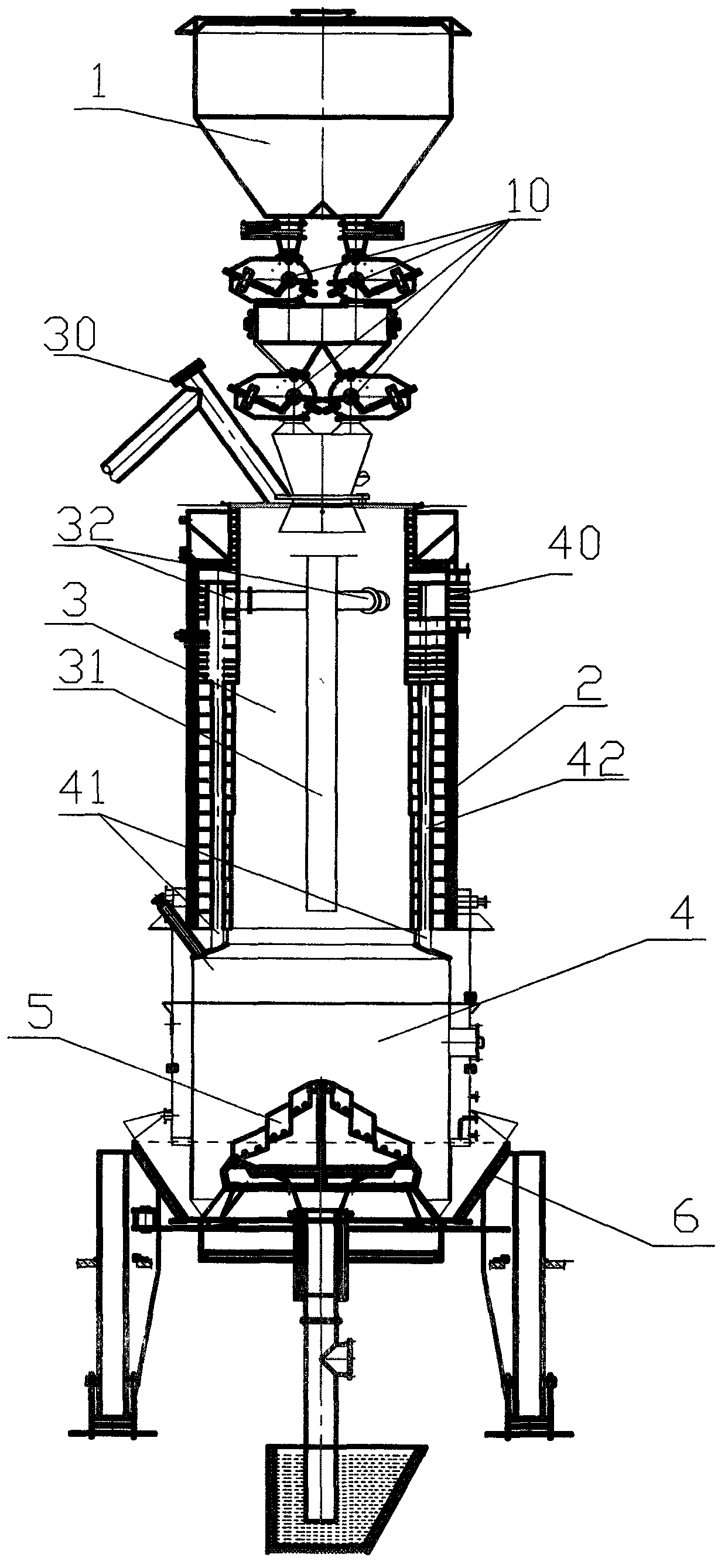
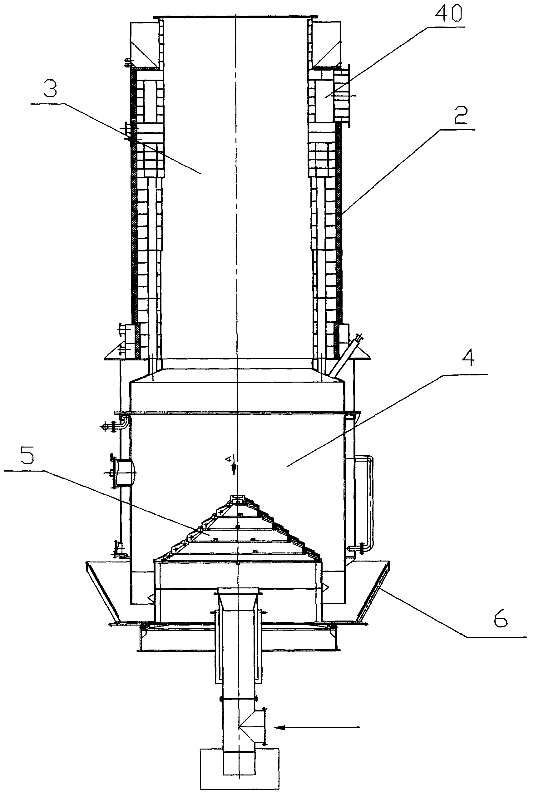
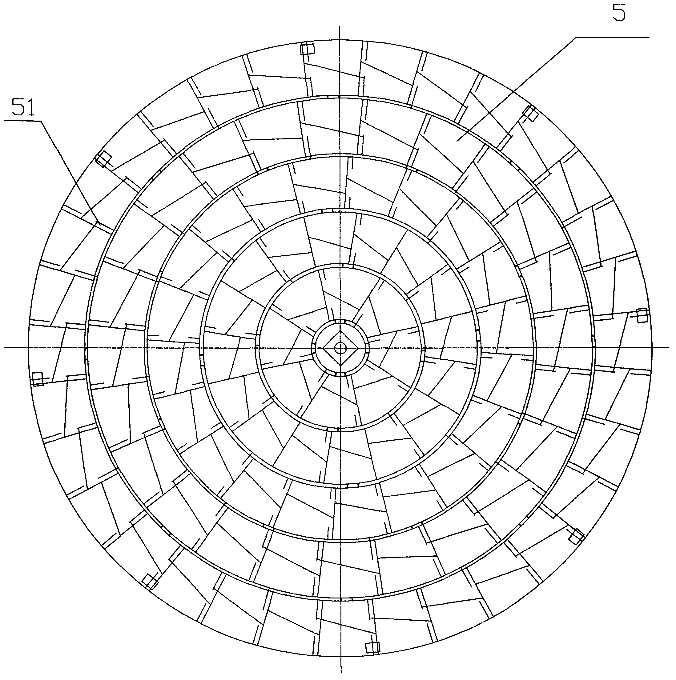
[0019] refer to figure 1 , figure 2 , image 3 , Figure 4 , Figure 5 , Figure 6 , a two-stage gas generating device, comprising a coal bunker 1 and a furnace body 2 composed of a retort section 3, a gasification section 4, a grate 5 and an ash discharge device 6, and a gas outlet pipe 30 is arranged on the top of the retort section 3 Lead out the carbonization low-temperature high-calorific value gas in the upper stage, and a center pipe 31 is arranged at the center of the carbonization section 3, and the center pipe 31 is used to collect the lower-stage high-temperature gas produced in the reaction layer. Since the center pipe 31 is arranged in the center of the carbonization section 3, The high-temperature gas collected in the lower section of the central tube 31 can dry and dry the coal around the central tube 31 during the transportation process, and it is a thermal processing radiated from the center to the periphery, so as to avoid uneven heating and dry distilla...


PUM


Abstract

The invention discloses a two-stage coal gas generating device, which solves the problems of the traditional coal gas generator that the air distribution is non-uniform, the utilization rate of the coal is low, and the gas yield is low. A grate bar of a six-layer composite structure is adopted, so that the maximal diameter of the grate bar can reach 3.22m, the inner diameter of an entire furnace can reach 4 to 20m, the utilizable area inside the entire furnace is increased, the coal gas output of a single furnace is improved, two elongated air distribution ports, i.e. an upper air distribution port and a lower air distribution port with inclination angles of 27 DEG and 22 DEG are respectively arranged in an air outlet of the grate bar, the elongated upper air distribution port and the elongated lower air distribution port are staggered to each other to integrate the air distribution of an upper large inclination angle and the air distribution of a lower small inclination angle, so that the gasification agent is more uniformly distributed in the generator through the alternating air distribution, the gasification is more adequate, the heat efficiency is greatly improved, the energy is saved, the air distribution in the entire generator is uniform, the coal gas yield is high, the coal gas quality is stable, less land area is occupied, and the energy conservation and consumption reduction can be better realized; and the two-stage coal gas generating device is applicable to different two-stage coal gas generators.

Description

technical field [0001] The invention relates to a gas generating device, in particular to a double-stage gas generating device. Background technique [0002] At present, the specifications of the two-stage gasifiers most used in the market are below Φ4.0m, generally Φ2.0m, Φ3.2m, Φ3.4m, Φ3.6m, etc. Due to the technical limitations of the grate blast system, the two-stage gasifiers of these specifications have uneven distribution of blast air, resulting in uneven heating in the furnace, technical defects of weak side fire and strong medium fire, and relatively low utilization rate of coal. Low, generally only up to 70% - 80%, and the gas production is relatively small, so the production cost is relatively high, and in the case of the same gas production, the two-stage gas generator with a specification below Φ4.0m Furnaces need more units to achieve the same output, and because the overall production equipment system of the gas generator device is relatively large, more unit...

Claims


Application Information

Patent Timeline
IPC IPC(8): C10J3/60C10J3/82C10J3/66C10J3/20C10J3/36C10J3/72
CPCY02P20/10
Inventor 赵秋生
Owner FOSHAN WELKIN MACHINERY
Learn More