A prefabricated concrete frame beam-column joint structure

A technology of prefabricated concrete and beam-column connection, which is applied in the direction of building construction and construction, can solve the problems of poor force transmission performance of steel strand lap connection, increase the difficulty of prefabrication and installation, and poor economic indicators, and achieve improvement The effects of earthquake resistance, cost reduction, and convenience for hoisting in place

Inactive Publication Date: 2015-09-09
SOUTHEAST UNIV
View PDF6 Cites 1 Cited by
  • Summary
  • Abstract
  • Description
  • Claims
  • Application Information

AI Technical Summary

Problems solved by technology

[0003] In the above-mentioned known connection structure, grooves are provided at the beam ends and the steel strands in the grooves are used as hooks, and U-shaped steel bars and steel strands are provided for lap connection. It is difficult to locate U-shaped steel bars in field construction. The force transfer performance of the overlapping connection between the tendon and the steel strand in the groove at the end of the beam is poor, resulting in relatively small ductility of the joint; for the head of the steel bar that protrudes a certain length from the lower part of the beam end, it is treated as a hook and directly anchored into the joint In the structure of the area, when the steel bars at the bottom of the beam extend into the joint area in different directions, there is often the problem of beam-to-beam or beam-to-column steel bars colliding with each other, which increases the difficulty of prefabrication and installation; The performance index is not good, and it is easy to rust, etc., which limits its popularization and application

Method used


Image

  • A prefabricated concrete frame beam-column joint structure
  • A prefabricated concrete frame beam-column joint structure
  • A prefabricated concrete frame beam-column joint structure

Examples


Embodiment Construction

[0023] The present invention will be further described below in conjunction with the accompanying drawings.

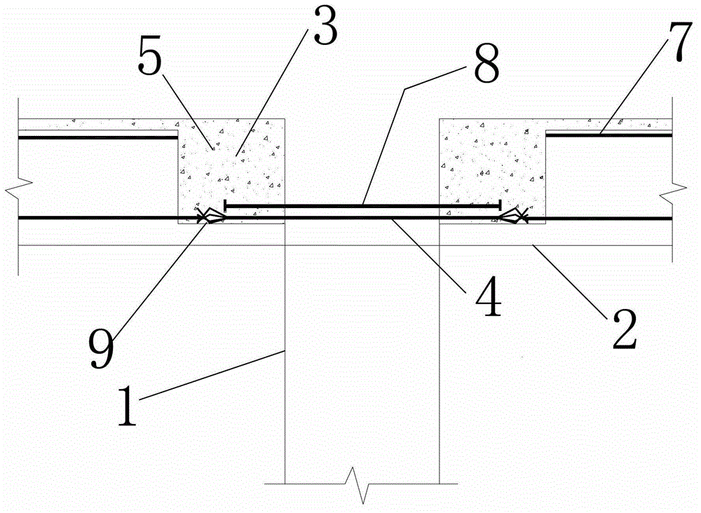
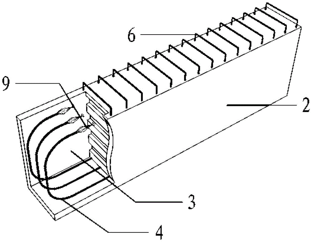
[0024] Such as figure 1 , 2 , 3, and 4 show a prefabricated concrete frame beam-column joint structure, including precast concrete columns 1 and precast concrete beams 2, and the precast concrete beams 2 and precast concrete columns 1 are matched and installed to form beam-column joints ; The precast concrete beam 2 is provided with a U-shaped groove 3 toward the end of the precast concrete column 1, and the precast concrete beam 2 is provided with a prestressed steel strand 4 along the length direction, and the prestressed steel strand The tail section of 4 protrudes from the cavity of the U-shaped groove 3, and its tail end is provided with an embossed anchor 9, and the embossed anchor 9 is anchored in the beam-column node or other U-shaped grooves of the beam-column node 3; the beam-column joint is fixed by pouring concrete 5 in the beam-column joint area.

[002...


PUM


Abstract

The invention discloses a beam-column joint structure of a prefabricated concrete frame. The beam-column joint structure comprises prefabricated concrete columns and prefabricated concrete beams; the prefabricated concrete beams and the prefabricated concrete columns are fittingly mounted and form beam-column joints; and U-shaped grooves are arranged at ends, which face the prefabricated concrete columns, of the prefabricated concrete beams, prestress steel stranded wires which extend along length directions are arranged in the prefabricated concrete beams, tail sections of the prestress steel stranded wires extend out of cavities of the U-shaped grooves, bulb anchors are arranged at tail ends of the prestress steel stranded wires and are anchored in the beam-column joints or other U-shaped grooves of the beam-column joints, and the beam-column joints are fixed by means of pouring concrete in beam-column joint areas. The beam-concrete joint structure has the advantages that the flexibility of the steel stranded wires in the grooves at the ends of the beams is sufficiently utilized, so that the steel stranded wires can bypass column ribs and beam ribs to be directly anchored in the beam-column joint areas, the ductility of the joints of the prefabricated frame is improved, the columns are strong while the beams are weak, construction is simplified, the manufacturing cost is reduced, and the beam-column joint structure can be directly applied to engineering practice.

Description

technical field [0001] The invention relates to a prefabricated and assembled concrete frame beam-column connection node structure, which belongs to the technical field of concrete frame structures in construction engineering. Background technique [0002] In order to meet the seismic performance requirements of the prefabricated concrete frame structure, the reliability of the connection between prefabricated columns and prefabricated beams is generally resolved through relevant structural measures. The currently known connection structure includes a groove at the end of the beam, a hook for the prestressed steel strand at the bottom of the beam, and a U-shaped steel bar for lap connection with the hook steel strand in the groove and the node area. The connection node of cast-in-place concrete; or the connection structure of cast-in-place concrete at the node, where a stepped corbel is placed at the end of the beam, and a certain length of ordinary steel bar with a hook pro...

Claims


Application Information

Patent Timeline
Patent Type & Authority Patents(China)
IPC IPC(8): E04B1/58
Inventor 郭正兴于建兵刘家彬
Owner SOUTHEAST UNIV
Why Eureka
Try Eureka