Pneumatic designing method of counter rotating compressor combining pumping of boundary layer

A technology of aerodynamic design and boundary layer, which is applied in the direction of mechanical equipment, machine/engine, liquid fuel engine, etc., can solve the difficulties in the design of suction pipes, the failure to fully utilize the load capacity of the suction stage of the boundary layer, and the decrease in blade strength, etc. question

Active Publication Date: 2013-07-10
HARBIN INST OF TECH
View PDF0 Cites 14 Cited by
  • Summary
  • Abstract
  • Description
  • Claims
  • Application Information

AI Technical Summary

Problems solved by technology

[0020] The present invention solves the problems that the existing axial flow compressor does not make full use of the boundary layer suction to improve the load capacity of the stage, and that the design of the suction pipe is difficult and the strength of the blade is reduced when the boundary layer suction is performed in the rotating parts.

Method used


Image

  • Pneumatic designing method of counter rotating compressor combining pumping of boundary layer
  • Pneumatic designing method of counter rotating compressor combining pumping of boundary layer
  • Pneumatic designing method of counter rotating compressor combining pumping of boundary layer

Examples


Embodiment Construction

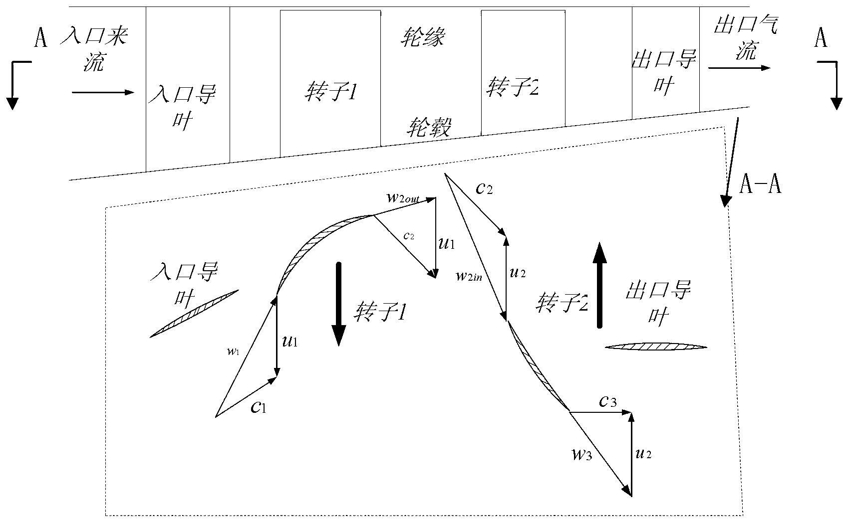
[0058] In actual design, according to the performance requirements of the engine as a whole. Usually the following parameters are given. Design speed, including the first row of rotor speed u 1 and the rotor speed u in the second column 2 ;Design load, including the first row of rotor design load Δw u1With the design load of the second column rotor Δ2w u2 ;Axial speed at the rotor inlet of the first column c 1z , the axial velocity c of the stator exit of the second column 5z . In addition, for the first row of rotors, the pre-swirl can be given according to its inlet Mach number requirements, but when the first row of rotors is already transonic or supersonic under the premise of axial air intake, usually direct axial air intake, that is For the first-stage moving blade, the inlet velocity triangle is known, namely u 1 , c 1 ,w 1 are known. Therefore the realization step of this invention is as follows:

[0059] Step 1. Using the high-efficiency and high-load rotor...


PUM


Abstract

The invention relates to a pneumatic designing method of a counter rotating compressor combining the pumping of a boundary layer, which belongs to the technical field of the pneumatic design of a high-load axial-flow compressor, and can effectively solve the series of problems when two columns of rotors of the existing counter rotating axial-flow compressor directly rotate in a counter way, and also can prevent the pumping of the boundary layer from being carried out in a rotor. By utilizing a way for enhancing the outlet axial speed of a movable blade, a first column of rotors can be pneumatically designed under a given load pneumatic design target; the axial component speed of an absolute speed in an inlet of a second column of movable blades can be determined according to the rotation speed of a second column of movable blades; a pre-rotation angle of the inlet of a second column of rotors is calculated according to the inlet mach number demand of the second column of rotors and the load of the first column of rotors; and the radial outlet speed and the radial inlet speed in two columns of stationary blades of the second column of rotors can be solved according to the outlet axial speed and the outlet airflow angle of the second column of rotors and the outlet axial speed of a second column of stators. Due to the adoption of the pneumatic designing method, the working capacity of each column of rotors of the counter rotating compressor can be adequately tapped, and the high-load pneumatic design of the counter rotating compressor can be realized.

Description

technical field [0001] The invention relates to an aerodynamic design method of a counter-rotating compressor combined with boundary layer suction, and belongs to the technical field of aerodynamic design of a high-load axial flow compressor. Background technique [0002] This patent involves three aspects of technology. They are counter-rotating compressor technology, boundary layer suction technology, and high-efficiency and high-load rotor blade design technology based on axial speed increase. [0003] 1. Counter-rotating compressor technology [0004] For the turbine, considering that the air flow in the turbine is generally in the forward pressure flow, so the stator blades between the two rows of rotors can be reduced to directly counter-rotate without reducing the load of the stage, so that the engine has a compact structure and a low weight. Descending, the thrust-to-weight ratio increases. In addition, counter-rotation technology can also reduce the resultant tor...

Claims


Application Information

Patent Timeline
Patent Type & Authority Applications(China)
IPC IPC(8): F04D29/38
Inventor 王松涛胡应交
Owner HARBIN INST OF TECH
Why Eureka
Try Eureka