Ethernet flow control device and method based on microwave transmission

A microwave transmission and Ethernet technology, applied in transmission systems, digital transmission systems, data switching networks, etc., can solve problems such as impact, high-priority service delay and delay jitter performance cannot be guaranteed, and achieve the effect of improving performance

Inactive Publication Date: 2013-07-10
ZTE CORP
View PDF5 Cites 11 Cited by
  • Summary
  • Abstract
  • Description
  • Claims
  • Application Information

AI Technical Summary

Problems solved by technology

This method solves the problem of transmission reliability very well, but the delay and delay jitter performance of high-priority services cannot be guaranteed at all, and will be greatly affected

Method used


Image

  • Ethernet flow control device and method based on microwave transmission
  • Ethernet flow control device and method based on microwave transmission
  • Ethernet flow control device and method based on microwave transmission

Examples


Embodiment 1

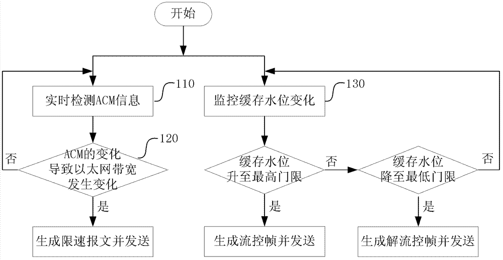
[0039] Such as figure 1 shown, including the following steps:

[0040] Step 110, detecting the ACM information of the wireless link in real time;

[0041] The above-mentioned ACM information is a signal of several bits (for example, 4 bits), which is given by the modem chip and used to indicate the modulation and coding mode of the frame after the current frame.

[0042] Step 120, when the change of ACM causes the bandwidth of the wireless link Ethernet to change, generate a rate limit frame and send it to the data sending end;

[0043] The above ACM information has a corresponding relationship with the wireless link bandwidth, as shown in Table 1. When the change of ACM causes the wireless link bandwidth to change, the generated rate limit frame carries the latest wireless link bandwidth information and sends it to the data sender, who then configures a new transmission rate. The data sending end is, for example, a switching chip.

[0044] Table 1 Correspondence between A...

Embodiment 2

[0052] This embodiment introduces the flow control device for implementing the method in Embodiment 1 above, such as figure 2 As shown, it includes ACM real-time detection module, rate limit frame generation module, sending buffer real-time monitoring module, flow control frame generation module, and scheduling module, wherein:

[0053] The ACM real-time detection module is used to detect the ACM information of the wireless link in real time, and when it is judged that the change of the ACM causes the Ethernet bandwidth to change, the speed limit frame generation module is triggered;

[0054] The speed limit frame generation module is used to generate a speed limit frame based on the trigger of the ACM real-time detection module, and send it to the scheduling module;

[0055] The sending buffer real-time monitoring module is used to monitor the change of the buffer water level in real time while the ACM real-time detection module detects the ACM information of the wireless li...

application example 1

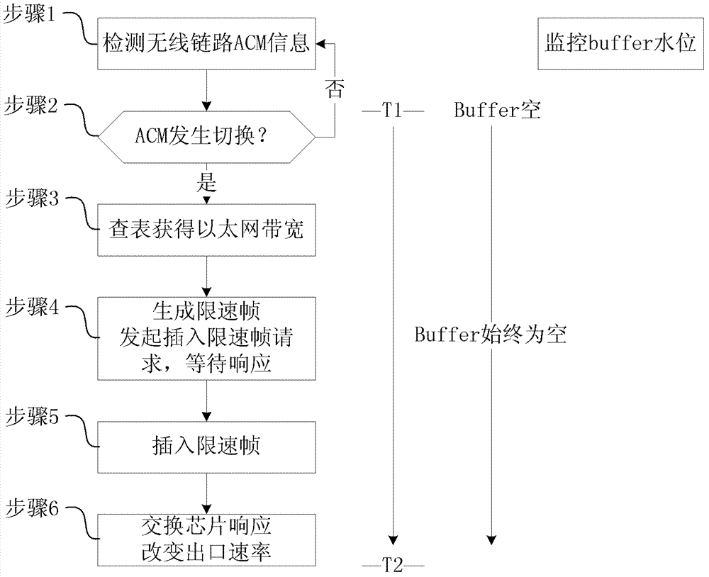
[0063] In this example, the ACM is switched from a low modulation mode to a high modulation mode, and the Ethernet bandwidth of the wireless link becomes larger. The implementation steps are as follows image 3 shown.

[0064] Step 1. The ACM real-time detection module detects the ACM information of the wireless link in real time. Since the ACM information indicates the modulation mode of the wireless link after one frame, the ACM real-time detection module can compare it with the current ACM information by analyzing the detected ACM information. Compare the modulation modes of the wireless link to obtain the information of when the ACM will switch and which modulation mode it will switch to;

[0065] Step 2, the ACM real-time detection module compares the ACM information currently received with the ACM information received last time, if it is different and the current ACM value is greater than the last ACM value, then it is judged that the ACM is switched and the switching di...


PUM


Abstract

The invention discloses an Ethernet flow control device and method based on microwave transmission. The Ethernet flow control method includes the steps: detecting adaptive coded modulation (ACM) information of wireless links in real time, and generating rate-limiting frames and sending the rate-limiting frames to a data sending end when the Ethernet bandwidth is changed due to changes of ACM; and monitoring changes of a buffering water level in real time while the ACM information is detected, generating flow-control frames and sending the flow-control frames to the data sending end when the buffering water level rises to a highest threshold, and generating flow-control removing frames and sending the flow-control removing frames to the data sending end when the buffering water level falls to a lowest threshold. The Ethernet flow control device comprises an ACM real-time detecting module, a rate-limiting frame generating module, a sending and buffering real-time monitoring module, a flow-control frame generating module and a scheduling module. According to the Ethernet flow control device and method, a sending rate is adaptively adjusted through combination of flow control and exit rate limiting, and time delay of high priority services can be guaranteed.

Description

technical field [0001] The invention relates to the technical field of microwave data communication, in particular to an Ethernet flow control device and method based on microwave transmission. Background technique [0002] Ethernet is currently the most widely used LAN technology. Because of its simplicity, low cost, strong scalability, and good integration with IP networks, the application of Ethernet technology is moving from the enterprise internal network to the public telecommunication network. Ethernet access refers to the combination of Ethernet technology and integrated wiring, as the access network of the public telecommunication network, to directly provide users with various IP-based service channels. The essence of Ethernet is a layer-2 medium access control technology, which can be transmitted on Category 5 lines, and can also be combined with other access media to form a variety of broadband access technologies. [0003] With the rapid development of the Int...

Claims


Application Information

Patent Timeline
Patent Type & Authority Applications(China)
IPC IPC(8): H04L12/811H04L47/30
CPCH04L47/263H04L47/30H04L47/266
Inventor 林晓静沈绍清赵曰恒程文薛巨伟
Owner ZTE CORP
Why Eureka
Try Eureka