Combined interlayer pulley vertical hinged lead door and corresponding planer steel plate track

A combined type and pulley technology, which is applied to the special equipment of doors/windows, door leaves, windows/doors, etc., can solve the problems of patients trapped in the machine room, difficult to rescue, easy to damage the motor, etc., to achieve smooth, stable and light operation, It is not easy to fail, and the surface is smooth and stable.

Inactive Publication Date: 2013-07-17
ZHEJIANG OCEAN UNIV
View PDF4 Cites 8 Cited by
  • Summary
  • Abstract
  • Description
  • Claims
  • Application Information

AI Technical Summary

Problems solved by technology

At present, there are two problems with the use of track-type sliding jaws: one is that it occupies a large area, and the width of the jaws plus the movement occupies more than 3 meters of space; the second is that the track needs a trench that is more than 3 meters long and 20 centimeters wide. , affecting the entry and exit of personnel and equipment, even if the trench is covered with crawlers, it is still incompletely level with the ground and it is inconvenient to walk. Small ground area was once very popular, but because the movable end of the existing flat-opening jaw door is suspended in the air, most of the weight of the jaw door is borne by the door shaft, and the door bearing is subjected to excessive shear force, and the door shaft is easily deformed over time , so that the bottom edge of the movable end of the jaw door falls and rubs against the ground, causing jamming (the jaw door cannot be opened), and the power of the swing door is on the side of the door shaft, and the moment arm is very short, which requires a lot of power to start the jaw door. easy to damage the motor
Swing doors are generally opened inwards, and the power system for opening the door, including the motor and power transmission system, is inside the door. Once a jammed door occurs, the patient will be trapped in the machine room, and it is difficult for the staff to rescue it outside.

Method used


Image

  • Combined interlayer pulley vertical hinged lead door and corresponding planer steel plate track
  • Combined interlayer pulley vertical hinged lead door and corresponding planer steel plate track
  • Combined interlayer pulley vertical hinged lead door and corresponding planer steel plate track

Examples


specific Embodiment approach

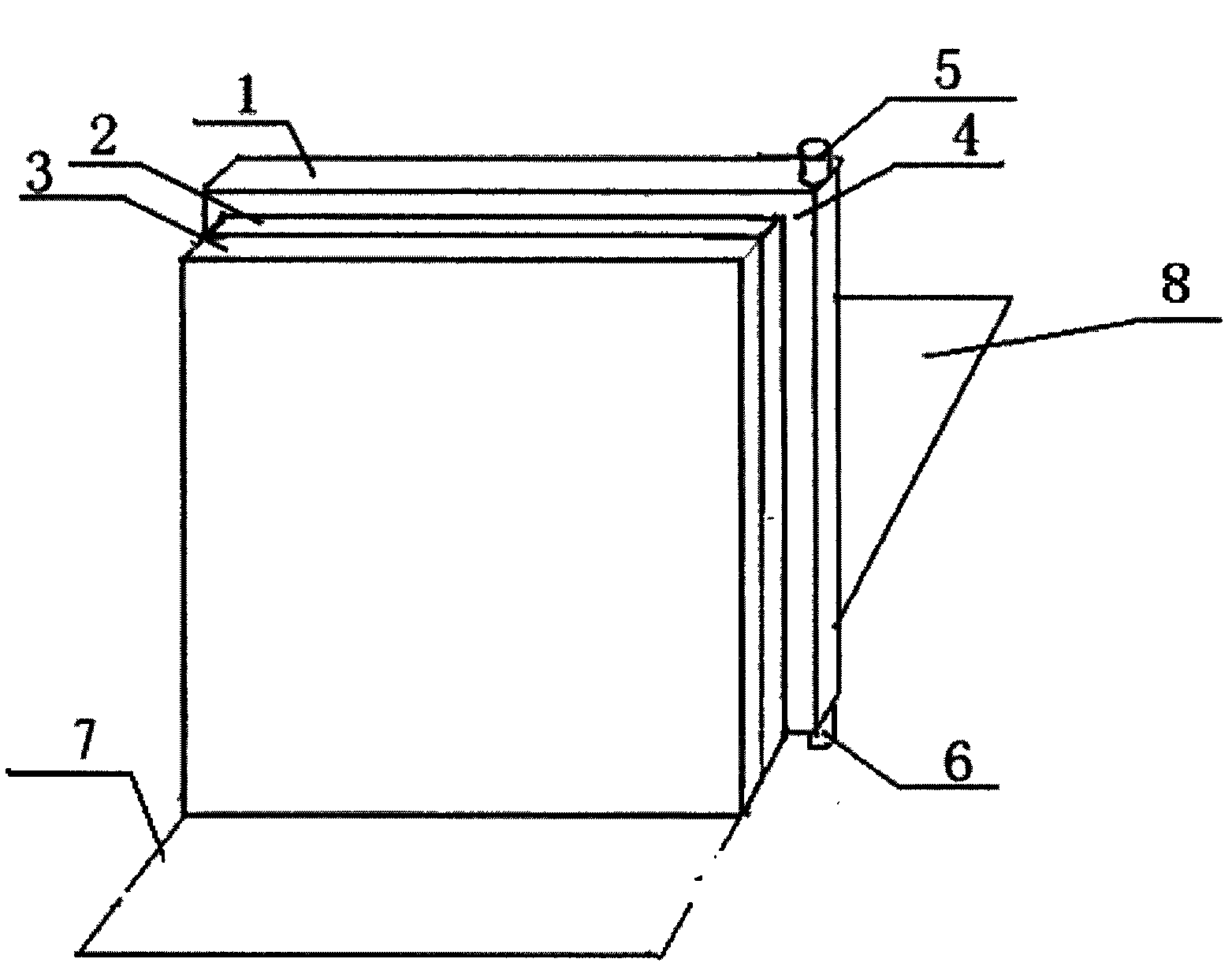
[0013] figure 1 Embodiment 1 shown: the covering layer (1) of the lead door is 2-10 cm higher than the embedding layer (3) and the steel connecting frame layer (2), and is also 2-10 cm wider than the embedding layer and the steel connecting frame layer, so When the embedded layer and the steel connecting frame layer are embedded in the doorway, the covering layer can block the rays leaking between the doorway and the embedded layer.

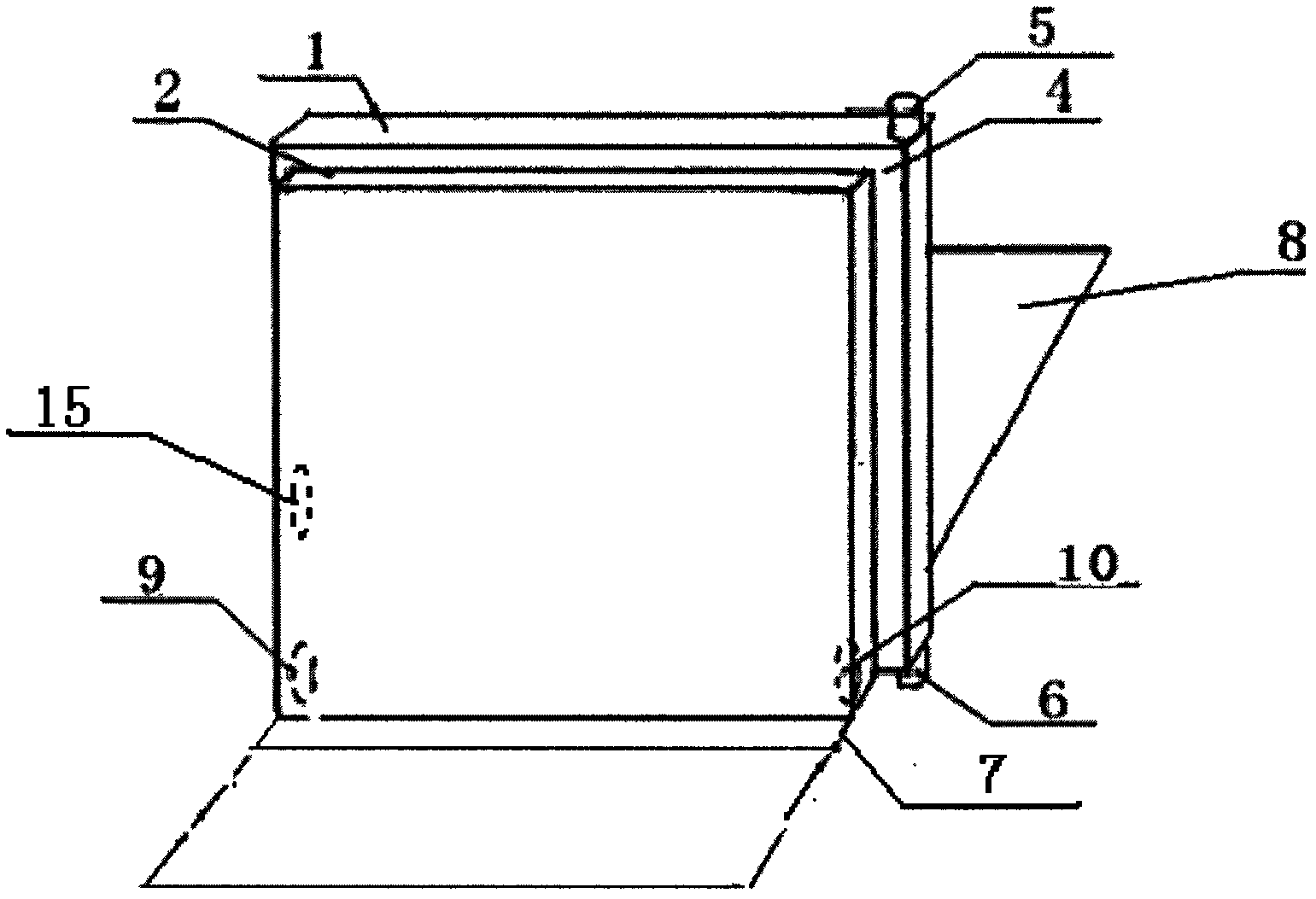
[0014] figure 2 Example 2 is shown: the pulley (9) on the moving side of the bottom of the steel connecting frame and the vertical movement of the inner and outer surfaces of the jaw, the power system (15) above the pulley, and the pulley (10) on the side of the door shaft and the vertical movement of the inner and outer surfaces of the jaw .

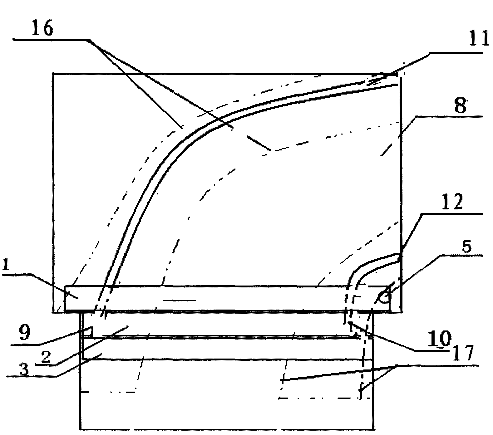
[0015] image 3 , Figure 4 Shown embodiment 3: when the jaw moves, the track of the motion of the pulley and the plane steel plate track laid along the track: represent the side pulley track of the j...


PUM


Abstract

The invention relates to a combined interlayer pulley vertical hinged lead door and a corresponding planer steel plate track. The body of a vertical hinged lead door is divided into two layers, i.e. a covering layer (1) and an embedding layer (2), which are connected by a steel connecting frame layer (3), in thickness direction. The covering layer is slightly larger than a door way in area, and the embedding layer and the steel connecting frame layer are slightly smaller than the door way in area. Pulleys (9, 10) moving along the direction vertical to the inner and outer faces of the lead door are respectively arranged on left and right edges of the lower side of the steel connecting frame layer, and a power system (15) is arranged above the pulleys on the moving side of the lead door. A reinforced concrete base with the thickness more than 20cm is poured below the lead door moving scope and on the ground in a certain range around the lead door moving scope, parts of two pulley tracks (11, 12) of the lead door are added with thick arched base rib beams (13, 14) when the base is poured, and planer steel plate tracks (16, 17) adaptive to the pulley tracks (11, 12) in shape are embedded in the faces of the arched base rib beams.

Description

technical field [0001] The invention relates to a combined sandwich pulley swing jaw and corresponding flat steel plate track, which can enhance the barrier function of the jaw, reduce the running resistance and mechanical failure of the jaw, decompose the weight of the jaw, and facilitate the manufacture, transportation, and maintenance of the jaw. Installation, maintenance and use, and the flat steel plate track is at the same level as the surrounding ground, which is convenient for personnel and equipment to enter and exit. Background technique [0002] The lead door of the accelerator room in the radiotherapy department weighs several tons. How to ensure its smooth operation is a big problem. At present, there are two problems with the use of track-type sliding jaws: one is that it occupies a large area, and the width of the jaws plus the movement occupies more than 3 meters of space; the second is that the track needs a trench that is more than 3 meters long and 20 cent...

Claims


Application Information

Patent Timeline
Patent Type & Authority Applications(China)
IPC IPC(8): E06B5/18E06B3/70E06B3/36E06B7/00
Inventor 王崇宇刘苗生刘泰华
Owner ZHEJIANG OCEAN UNIV
Why Eureka
Try Eureka