Method for cooling turbine disc and moving blade of combustion gas turbine

A technology for gas turbines and turbine disks, which is applied in the direction of blade support components, machines/engines, mechanical equipment, etc. It can solve the problems of large thermal stress on turbine moving blades, reduce thermal stress, meet the sealing function, and ensure the flow of cooling air Effect

Inactive Publication Date: 2013-07-17
BEIJING HUAQING GAS TURBINE & INTEGRATED GASIFICATION COMBINED CYCLE ENG TECH
View PDF6 Cites 14 Cited by
  • Summary
  • Abstract
  • Description
  • Claims
  • Application Information

AI Technical Summary

Problems solved by technology

[0004] However, since the air used to cool the swirling blades needs to pass through the intercooler, a large pressure loss will inevitably occur. However, the cooling of the turbine moving blades requires a high pressure of the cooling air to ensure the cooling air flow
At the same time, because the cooled air may generate too low temperature, it will cause excessive thermal stress when the turbine rotor blades are cooled.

Method used


Image

  • Method for cooling turbine disc and moving blade of combustion gas turbine
  • Method for cooling turbine disc and moving blade of combustion gas turbine
  • Method for cooling turbine disc and moving blade of combustion gas turbine

Examples


Embodiment Construction

[0020] The principle, structure and specific implementation of the present invention will be further described below in conjunction with the accompanying drawings.

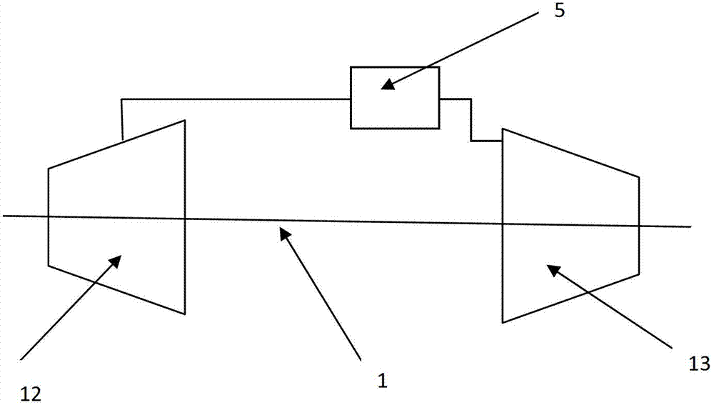
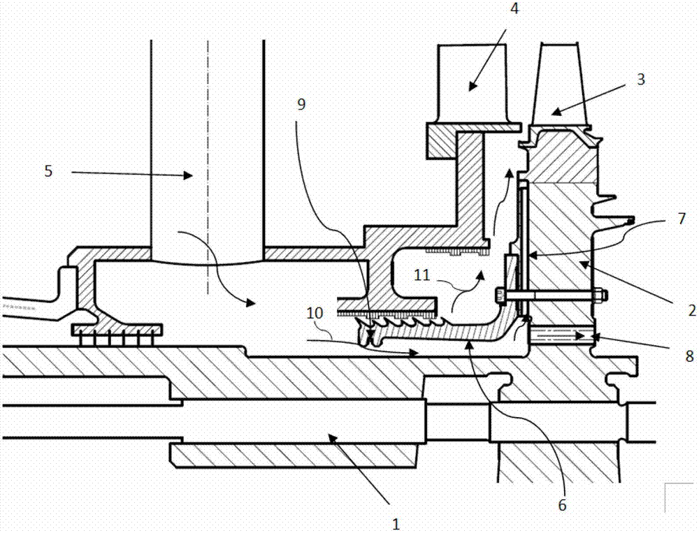
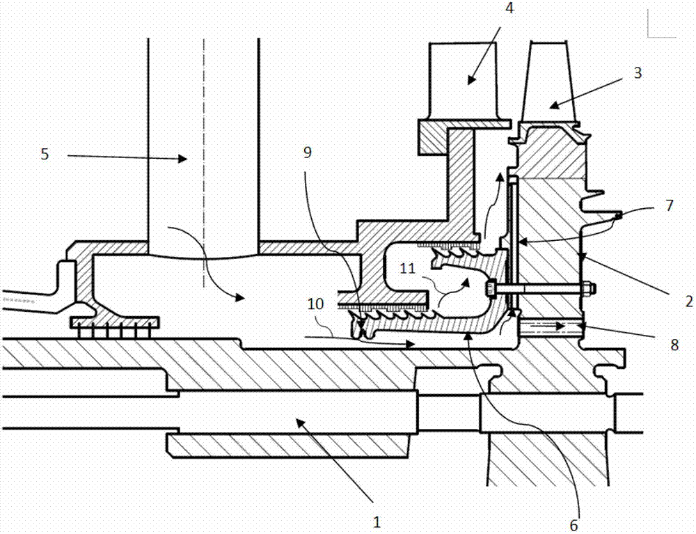
[0021] figure 2 It is a schematic diagram of the embodiment of the present invention adopting a single-layer sealing structure, and the cooling process is as follows: the high-temperature and high-pressure air extracted from the compressor 12 is cooled by the intercooler 5 and then separated into two airflows by the sealing structure 6, one for cooling Airflow 10, the other is sealing airflow 11. The sealing structure 6 adopts a single-layer sealing structure, which is composed of a ring sealing component, and is fixed on the first-stage turbine disk 2 by bolts, and the axis of the sealing structure coincides with the axis of the rotor 1; A radial channel 7 is arranged near the sealing structure, and a shock absorbing ring 9 is installed at the front end of the sealing structure. The radial channel 7 plays a ro...


PUM


Abstract

The invention relates to a method for cooling a turbine disc and a moving blade of a combustion gas turbine. High-temperature high-pressure air pumped out by an air compressor is divided into two air flows by a sealing structure after being cooled by an intercooler, wherein the two air flows are a cooling air flow and a sealing air flow; the cooling air flow is used for cooling a one-stage turbine moving blade and a one-stage turbine disc respectively, the other sealing air flow enters a channel between the one-stage turbine moving blade and a one-stage static blade to prevent gas from flowing backwards. According to the method, the one-stage turbine disc and the moving blade can be effectively cooled and the sealing effect of the front end of the one-stage turbine disc is achieved; besides, a radial channel in the one-stage turbine disc can achieve a rotary pump effect and a heat-exchange function of the cooling air, so that the cooling method can cool the one-stage turbine disc while performing pressurization and temperature rise on the cooling gas, the cooling air flow rate needed by the one-stage turbine disc and the one-stage turbine moving blade can be ensured, and the thermal stress of the one-stage turbine moving blade is reduced.

Description

technical field [0001] The invention relates to the field of gas turbines, in particular to a method for cooling a turbine disk and moving blades of a gas turbine. Background technique [0002] With the continuous innovation and development of modern gas turbine technology, in order to improve the overall thermal efficiency of the gas turbine, the temperature before the turbine continues to rise. As a high-speed rotating part, the turbine rotor blades work in an extremely high temperature environment. Due to the limitation of materials, only relying on the existing high-temperature resistant materials can no longer meet the actual needs. The turbine rotor blades must be cooled in a certain form. [0003] The air used to cool the turbine rotor blades generally comes from compressor extraction. As the cooling requirements become higher and higher, the demand for air extraction is also increasing, which will lead to a decrease in the thermal efficiency of the gas turbine. Ther...

Claims


Application Information

Patent Timeline
Patent Type & Authority Applications(China)
IPC IPC(8): F01D25/12F01D5/18
Inventor 于宁朱锦灿黄媛君
Owner BEIJING HUAQING GAS TURBINE & INTEGRATED GASIFICATION COMBINED CYCLE ENG TECH
Why Eureka
Try Eureka