Extracting tank with built-in partition plate

A technology of extraction tanks and partitions, which is applied in the field of pharmaceutical equipment, can solve the problems of poor reflux mixing effect and poor mixing effect, and achieve good stirring and mixing effects and enhanced extraction effects

Inactive Publication Date: 2013-07-24
汪振朴
View PDF8 Cites 5 Cited by
  • Summary
  • Abstract
  • Description
  • Claims
  • Application Information

AI Technical Summary

Problems solved by technology

[0005] The technical problem to be solved by the present invention is that in the prior art, the reflux liquid medicine only plays a mixing role on one side of the bottom of the tank, and the mixing effect on the materials at the rest of the position is poor, and the opening direction of the main swirl tube and the branch swirl tube Consistent, resulting in poor reflux mixing effect; and then proposed an extraction tank with a built-in partition to make the mixing degree of the liquid medicine and medicinal materials in the tank uniform

Method used


Image

  • Extracting tank with built-in partition plate
  • Extracting tank with built-in partition plate
  • Extracting tank with built-in partition plate

Examples


Embodiment 1

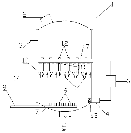
[0039] The extraction tank with built-in partition described in this embodiment is as figure 1 As shown, the tank body 1 is included, and the shape of the tank body 1 can be selected according to needs. In this embodiment, the tank body 1 is cylindrical. The upper part of the tank 1 is provided with a feed port 3, the top is provided with an air outlet 2, the bottom is provided with a slag outlet 5, and the lower part is provided with a liquid outlet 4 and an air inlet 7 (it can also be arranged at the bottom of the tank 1 ). The outer wall of the tank body 1 is provided with a heating interlayer 14, and the heating interlayer 14 can heat the tank body 1 through a built-in heating wire or passing steam into it. In this embodiment, the heating interlayer 14 is provided with There are heating wires (not shown in the drawings). Vent pipe 8, the vent pipe 8 stretches into the tank body 1 through the air inlet 7, and the connection between the vent pipe 8 and the air inlet 7 is a...

Embodiment 2

[0045] On the basis of the above-mentioned embodiment, this embodiment is such as Figure 4 As shown, a groove is provided along the inner wall of the tank body 1, and the partition 10 is embedded in the groove and is movably connected with it; the top of the partition 10 is provided with a rotating shaft 19 with a motor 20 for The partition plate 10 is controlled to rotate along the groove. Under the action of the motor 20, the rotating shaft 19 drives the partition plate 10 to rotate along the groove, so as to not only make the liquid medicine on the partition plate 10 more evenly distributed, but also play a good stirring and mixing effect on the liquid in the tank .

Embodiment 3

[0047] On the basis of the above examples, if Figure 5 As shown, the extraction tank described in this embodiment also includes a condenser 15 and a pressure relief pipe 16 with a pressure relief valve, the condenser 15 is provided with an inlet and an outlet, and the gas outlet 2 of the tank body 1 is connected to the The inlet of the condenser 15 communicates with the pressure relief pipe 16 , and the outlet of the condenser 15 communicates with the feed port 3 of the tank body 1 . When the pressure relief valve of the pressure relief pipe 16 is closed, the solvent vapor discharged through the gas outlet 2 is condensed and then returned to the tank for reuse through the feed port 3. On the one hand, the refluxed solvent after condensation can form a diluted solution locally. , can promote the rapid release of effective components in the medicinal materials. On the other hand, while the liquid in the tank is continuously recycled, the gaseous solvent is continuously replenis...


PUM


Abstract

The invention discloses an extracting tank with a built-in partition plate. The extracting tank is characterized in that the middle part of a tank body is provided with the partition plate for dividing an inner cavity of the tank body into upper and lower parts, downward liquid spraying pipes are distributed on the partition plate along the circumference, and air passing pipes are arranged at the other positions of the partition plate; the inner diameters of the liquid spraying pipes are gradually reduced from an inlet to an outlet, the outlets of the liquid spraying pipes on the same circumference and the clockwise rotation tangential speed along the circumference are obliquely downward in a 45-degree angle, or the outlets of the liquid spraying pipes on the same circumference and the anticlockwise rotation tangential speed along the circumference are obliquely downward in the 45-degree angle, and the outlet directions of the liquid spraying pipes on the adjacent circumferences are opposite; a coil is arranged above the partition plate, is close to the partition plate and is arranged along the inner circumference of the tank boy, and the bottom of the coil is provided with downward spraying holes; and a circulating pump comprises a pump inlet and a pump outlet, the pump inlet is connected with a liquid outlet, and the pump outlet passes through the side wall of the tank body so as to be communicated with the interior of the coil. A turbulence liquid medicine is formed in the extracting tank, the uniformly mixing degree of a liquid medicine and a medicinal material at each part in the tank is promoted, and effective active ingredients in the medicinal material are rapidly fully extracted.

Description

technical field [0001] The invention relates to an extraction tank equipped with a partition inside, belonging to the technical field of pharmaceutical equipment. Background technique [0002] In the field of pharmaceuticals, it is usually necessary to use extraction tanks to extract the active ingredients from the medicinal materials. The structure of the existing extraction tanks generally includes a tank body. The operating principle of the liquid port and slag discharge port is: put the medicinal material and solvent (usually water or ethanol) into the extraction tank through the feed port to mix, and then pass steam into the heating interlayer or directly into the tank Steam heats the mixture. During the heating process, the active ingredients are gradually separated from the medicinal materials and dissolved into the solvent to form a medicinal liquid. After a period of heating, the extraction is completed, and the medicinal liquid is directly discharged from the liqui...

Claims


Application Information

Patent Timeline
Patent Type & Authority Applications(China)
IPC IPC(8): B01D11/02
Inventor 章吉华田海林赵汉武林映
Owner 汪振朴
Why Eureka
Try Eureka