Light spreading in textiles

a textile and light technology, applied in the field of light emitting devices, can solve the problems of increasing absorption and appearance not always creating an appealing look, and achieve the effects of low light uniformity, minimal/decreased bright spots, and thin and flexible systems

Inactive Publication Date: 2018-02-22
SIGNIFY HLDG BV
View PDF0 Cites 5 Cited by
  • Summary
  • Abstract
  • Description
  • Claims
  • Application Information

AI Technical Summary

Benefits of technology

[0006]It is an object of the present invention to overcome these problems, and, inter alia, to provide a light emitting textile device and a method of making the device. It would be advantageous to achieve good levels of light uniformity with minimal / decreased bright spots and a thin and flexible system.
[0023]The mask may comprise scattering and / or reflective and / or absorbing structures or features. For example, the mask may comprise reflective white dots of ink. The mask may be heated or cured after it is deposited on the first light guide and over the at least one light emitting element. The mask may comprise a structure or structures which will absorb light which is reflected at steep angles and which will not be captured in the light emitting device and totally internally reflected therein. These structure(s) may comprise a light absorbing structure or structures. Said structure or structures may redirect light emitted from the at least one light emitting element and which is not totally internally reflected into the light guide or light guides. For example, the light absorbing structure or feature may comprise a black ring or rings. The black ring or rings may surround the rest of the mask, for example the black ring or rings may surround reflective white dots of ink. The light absorbing structure or structures may comprise an assembly of mirrors, for example an assembly of tilted mirrors. These arrangements serve to reduce the number of bright spots close to the light emitting element, e.g. LED or plurality of LEDs.
[0029]An advantage of the light emitting device according to the present invention is that the amount of light scattering from the textile surface in an uncontrolled manner is reduced thus reducing the occurrence of so-called bright spots. The light which is guided in the light guide can be extracted uniformly over an output surface of the light emitter. This may be achieved by using a pattern of extraction features and / or by local contact with the surface of the textile. Light may be extracted through the front surface and / or the back surface of the light guide. The surface through which the light is emitted from the light emitting device may be referred to herein as an output surface.

Problems solved by technology

However, LEDs are point source emitters, so a textile with integrated LEDs tends to appear as bright dazzling spots and the appearance does not always create an appealing look.
Many of these textile diffusers tend to absorb a substantial proportion of the light emitted by the light sources and / or to suffer from increasing absorption over time.

Method used


Image

  • Light spreading in textiles
  • Light spreading in textiles
  • Light spreading in textiles

Examples


example 1

on of a Light Emitting Device Comprising an LED, Water Soluble Sacrificial Material and a Black Ink Mask

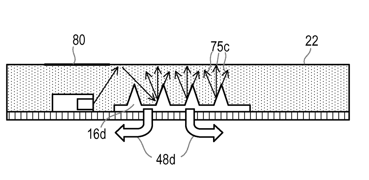
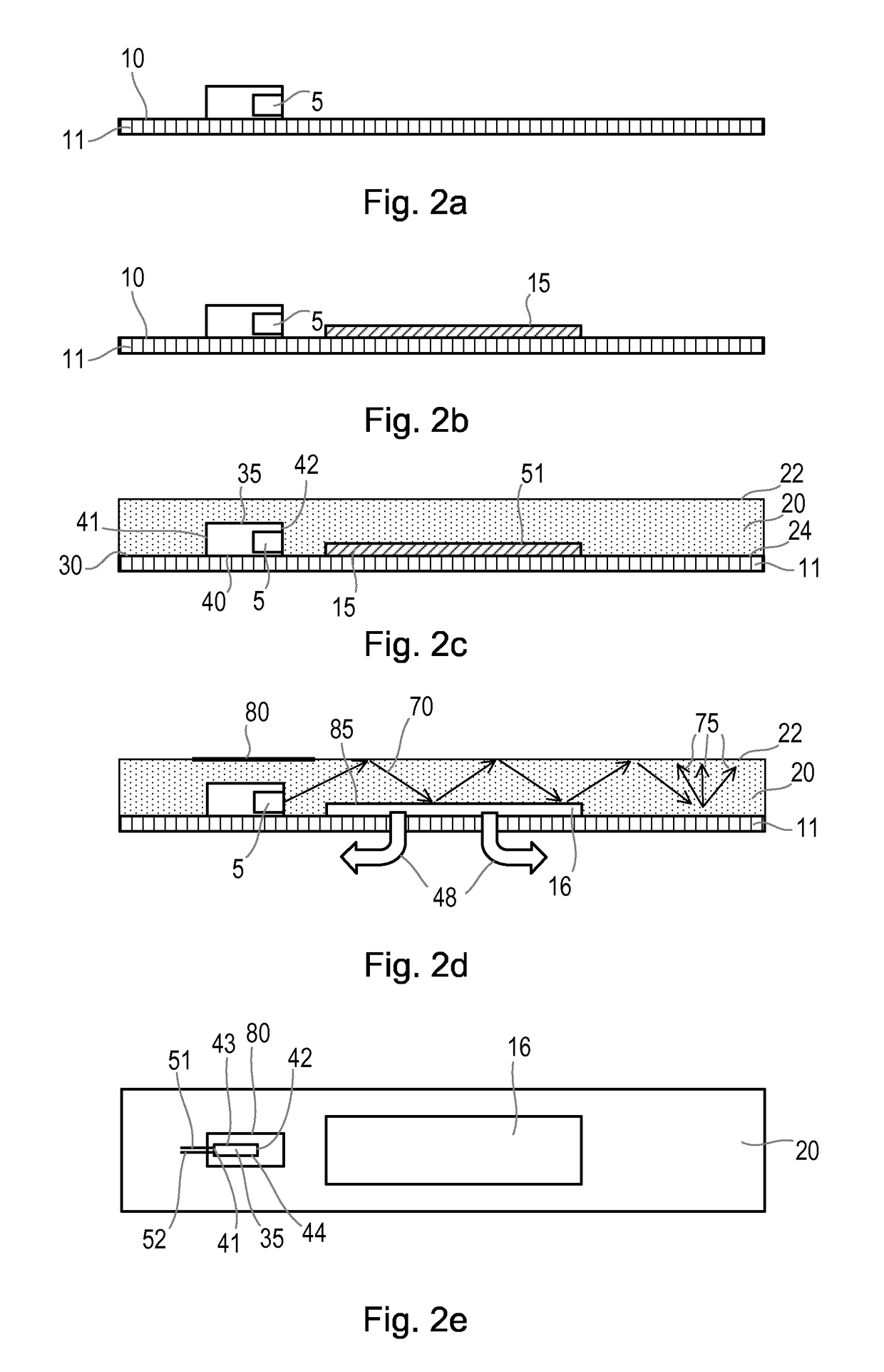
[0055]A light emitting device in accordance with the present invention is made as follows. An LED is secured to the surface of a fabric of woven polyester filaments by soldering to conductive wires that are woven inside the fabric. A water-soluble sacrificial layer of polyvinylalcohol is deposited on the surface of a fabric. The sacrificial layer is deposited by sputtering through a mask. A transparent layer of silicone (LSR 7060, available from Momentive) is applied to the surface of the fabric, the sacrificial layer and the LED by coating and is cured. The sacrificial layer is removed by exposing it to water. The permeability of the fabric allows the sacrificial layer to be removed by passage through the fabric. A mask comprising black ink is deposited on the layer of cured silicone and positioned over the LED by screen printing and is cured.

example 2

on of an Optical Model

[0056]A series of optical models was constructed in accordance with the present invention comprising the following elements:[0057]white diffusing reflective textile substrate;[0058]Nichia 204 side emitting LED, height=0.4 mm;[0059]silicone light guide, layer thickness=1 mm;[0060]white reflective mask over LED, radius=3.5 mm;[0061]black rings for angular selection, inner radius=2.5 mm, outer radius=3.5 mm;[0062]sacrificial layer made from wax, inner radius=3.5 mm, outer radius=8.0 mm.

[0063]The following models were constructed based on an LED arranged on a textile substrate and a light guide coating the light emitting element and the substrate:[0064](a) one LED, no mask, no air gap;[0065](b) one LED, one mask over the LED, no air gap;[0066](c) one LED, one mask over the LED, one air gap at interface between substrate and light guide.

[0067]The modeling system used was the optical ray trace software which is available from LightTools. The peak illuminance was calc...


PUM


Abstract

The present invention relates to a light emitting device comprising a light emitting element and a light guide arranged on a textile substrate and wherein one or more air gaps are present in the light guide at the interface with the textile substrate. The method also relates to a method of making the light emitting device and to various uses of the light emitting device.

Description

FIELD OF THE INVENTION[0001]The present invention relates to a light emitting device comprising a light emitting element and a light guide arranged on a textile substrate. The method also relates to a method of making the light emitting device and to various uses of the light emitting device.BACKGROUND OF THE INVENTION[0002]By integrating light sources, such as light emitting diodes (LEDs), into textiles and thereby creating light emitting electronic textiles, visual effects can be achieved. Efforts have also been made to form textile integrated display devices.[0003]However, LEDs are point source emitters, so a textile with integrated LEDs tends to appear as bright dazzling spots and the appearance does not always create an appealing look. For other applications, such as for light therapy uses, it may be important that the light is emitted in a more diffuse and homogeneous manner.[0004]Existing light emitting electronic textiles are often provided with a textile diffuser arranged o...

Claims


Application Information

Patent Timeline
Patent Type & Authority Applications(United States)
IPC IPC(8): F21V8/00
CPCG02B6/0021A61N2005/063A61N2005/0645A61N2005/0665G02B6/0065G02B6/0036G02B6/0031G02B6/0058G02B6/0095
Inventor CORNELISSEN, HUGO JOHANYU, JIANGHONGCENNINI, GIOVANNIGUERMONPREZ, PHILIPPE BERTRAND DANIELBOUVIER, PIERRE JEAN BERNARD
Owner SIGNIFY HLDG BV
Why Eureka
Try Eureka