Robot crus structure capable of imitating human body ankle motions by utilizing pull rods

A technology of robots and pull rods, applied in the direction of manipulators, manufacturing tools, etc., can solve the problems of difficult miniaturization, large number of components, damage, etc., and achieve the effect of strengthening stability and simulation

Inactive Publication Date: 2014-12-24
戴文钟
View PDF7 Cites 2 Cited by
  • Summary
  • Abstract
  • Description
  • Claims
  • Application Information

AI Technical Summary

Problems solved by technology

Although this robot 1 can flexibly bend the lower limb mechanism 12 through each driving module, there is a huge problem in this design, that is, because too many driving modules are used in the lower limb mechanism 12, and the driving modules are usually composed of Composed of a servo motor, a reduction mechanism, and the power transmission device between them, the number of components is too large and it is not easy to miniaturize. Therefore, the drive module of the previous stage must be able to bear the weight of the drive module of the next stage in order to achieve high efficiency, rigidity and load. Excellent dynamic characteristics compared to
[0004] by figure 1 The robot 1 is shown as an example. When the robot 1 is walking, the first driving module 121 and the second driving module 122 bear a relatively large external force, so a relatively large current must be used to maintain sufficient power. Driving the entire lower limb mechanism 12 to run, causing the drive modules 121 and 122 to consume too much power and be easily damaged by the high temperature generated by overload

Method used


Image

  • Robot crus structure capable of imitating human body ankle motions by utilizing pull rods
  • Robot crus structure capable of imitating human body ankle motions by utilizing pull rods
  • Robot crus structure capable of imitating human body ankle motions by utilizing pull rods

Examples


Embodiment Construction

[0031] The present invention will be further described below in conjunction with the accompanying drawings and embodiments.

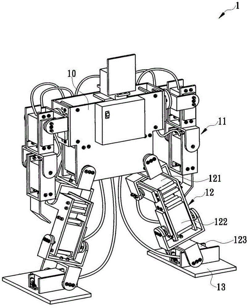
[0032] Such as Figure 4As shown, the present invention uses a pull rod to simulate the movement of the ankle of a robot, which is applied to a robot (not shown in the figure). At least two driving modules are arranged under the knee of the robot, and each driving module has an output shaft The positions correspond to each other, and the robot lower leg structure 4 includes a support frame 41, a foot plate 42, a frame 43, an inner shaft rod 44, a front pull rod 45 and two rear pull rods 46, wherein the support frame 41 is installed on the robot. There are two first pivotal joints 411 below the knee, and the top is provided with two first pivotal joints 411, and a first pivotal joint 412 is opened on each first pivotal joint 411, and the position of each first pivotal joint 412 corresponds to each drive module , in this embodiment, the structure of the ...


PUM


Abstract

The invention discloses a robot crus structure capable of imitating human body ankle motions by utilizing pull rods. The robot crus structure capable of imitating human body ankle motions by utilizing the pull rods comprises a supporting frame, a foot plate, a framework, an inner shaft rod and the two rear pull rods, wherein the supporting frame is arranged under knees of a robot and is adjacent to the positions of two driving modules, two first pivot joint portions are arranged at the top of the supporting frame, the foot plate is arranged at the bottom of the supporting frame, the framework is positioned between the two first pivot joint portions, outer shaft rods are respectively arranged at two corresponding sides of the framework, each outer shaft rod is in pivot joint with each first pivot joint portion and penetrates through each first pivot joint portion to be connected with each driving module, the inner shaft rod penetrates through the other two corresponding sides, a connection rod is arranged at one end of the inner shaft rod, two ends of each rear pull rod are respectively connected with the connection rod and the foot plate, when the outer shaft rods and the inner shaft rod are respectively driven to move, the framework and the connection rod respectively swing back and forth, and side to side, and the pull rods are similar to crus muscles of a human body and control the foot plate to make various ankle motions.

Description

technical field [0001] The invention relates to a robot lower leg structure which uses a pull rod to simulate the movement of the ankle of a human body. Background technique [0002] A robot is a general term for an automatic control machine (Robot). It is mainly used to assist people in various tasks that are highly dangerous, high-precision or require long-term repeated execution. Multi-joint robotic arm (robot arm) to improve the yield rate and manufacturing efficiency of the production line. Today, the application fields of robots are becoming more and more extensive. Whether it is semiconductor, metal processing, fan manufacturing, solar energy manufacturing, food processing and packaging, electronics, pharmaceuticals and other industries, various types of robots can be seen, which makes the industry Through the automation and mechanization of production, production efficiency, product capacity, operating costs and industrial safety requirements can be greatly improved...

Claims


Application Information

Patent Timeline
Patent Type & Authority Patents(China)
IPC IPC(8): B25J11/00
Inventor 戴文钟
Owner 戴文钟
Why Eureka
Try Eureka