LED (Light Emitting Diode) panel lamp

A technology of LED panel lights and light frames, applied in lighting devices, cooling/heating devices of lighting devices, light sources, etc., can solve the problems of large impact on lighting effects, poor lighting effects, high production costs, etc., and achieve good heat dissipation effect and distributed The effect of low density and low production cost

Inactive Publication Date: 2013-07-24
ZHEJIANG EMITTING OPTOELECTRONICS TECH
View PDF5 Cites 9 Cited by
  • Summary
  • Abstract
  • Description
  • Claims
  • Application Information

AI Technical Summary

Problems solved by technology

[0004] Based on this, it is necessary to solve the problems of uneven brightness of traditional LED panel lights, a large impact on the overall lighting effect after a single lamp is damaged, poor lighting effect after replacing some LED light sources, poor heat dissipation effect and high production cost, and provide An LED panel light with relatively uniform width, less impact on the overall lighting effect after a single lamp is damaged, no impact on lighting effect after replacing some LED light sources, better heat dissipation effect and lower production cost

Method used


Image

  • LED (Light Emitting Diode) panel lamp
  • LED (Light Emitting Diode) panel lamp

Examples


Embodiment Construction

[0018] The present invention will be described in detail below in conjunction with the accompanying drawings and specific embodiments.

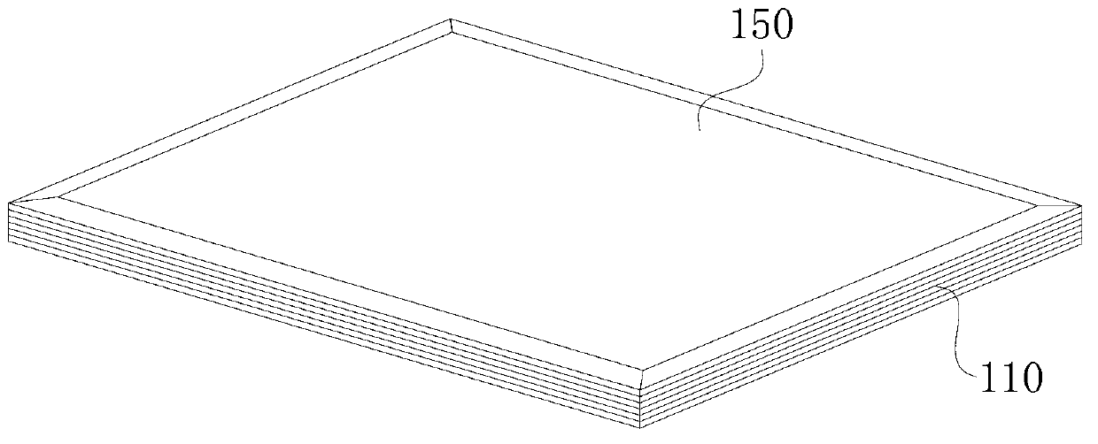
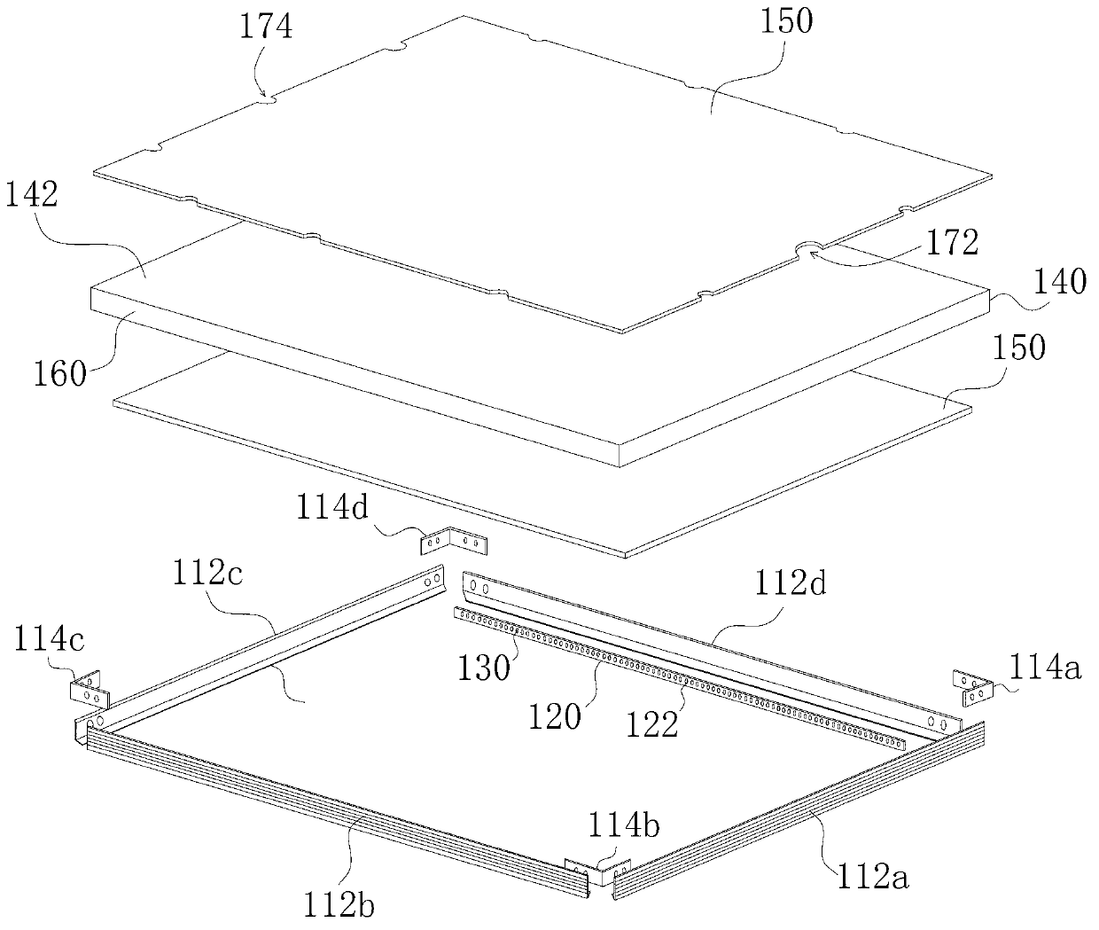
[0019] Such as figure 1 and figure 2 As shown, in one embodiment, an LED panel light includes a light frame 110 , a substrate 120 , a plurality of blue LEDs 130 , a light guide plate 140 , a diffusion plate 150 and a thin film 160 doped with phosphor. The light guide plate 140 and the diffuser plate 150 are embedded in the lamp frame 110 .

[0020] The lamp frame 110 includes four mounting plates 112a, 112b, 112c, 112d and four connecting pieces 114a, 114b, 114c, 114d. The four connecting pieces 114a, 114b, 114c, 114d are used to connect the four mounting boards 112a, 112b, 112c, 112d. Each mounting plate 112 a , 112 b , 112 c , 112 d has a plate edge 1122 extending toward the inner side of the lamp frame 110 , and the base plate 120 and / or the diffuser plate 150 are carried on the plate edge 1122 . In this embodiment, at least one mount...


PUM


Abstract

The invention relates to an LED (Light Emitting Diode) panel lamp, which comprises a lamp frame, a substrate, a plurality of blue-light LEDs, a light guide plate, a diffusion plate and a film doped with fluorescent powder. The light guide plate and the diffusion plate are embedded in the lamp frame. The substrate is arranged on the internal side surface of the lamp frame which faces to the side surface of the light guide plate. A plurality of cup troughs are abreast arranged on one side, which faces to the side surface of the light guide plate. of the substrate. One blue-light LED is installed in each cup trough. The blue-light LEDs are connected in series or in parallel. The film is attached onto the side surface, which faces to the blue-light LEDs, of the light guide plate. The light guide plate is provided with a light reflecting film. The light reflecting film is attached onto one surface of the light guide plate. The diffusion plate is arranged on the other surface, which is opposite to the light reflecting film, of the light guide plate. The LED panel lamp has the advantages that the emergent light is relatively uniform, the problem of glaring does not occur, the influence of a single damaged LED on the overall lighting effect is smaller, and the illuminating effect is better; since the blue-light LEDs are abreast arranged, the distribution density is lower and the heat dissipating effect is better; and since the blue-light LEDs are directly installed in the cup troughs, the production process is simple and the production cost is reduced.

Description

technical field [0001] The invention relates to the field of lamps, in particular to an LED panel lamp. Background technique [0002] LED (Light Emitting Diode, Light Emitting Diode) is a solid-state semiconductor device that can convert electrical energy into visible light. LED has the advantages of small size, low energy consumption, long life, pure light color, high brightness, low heat, environmental protection and low carbon, etc. It is internationally recognized as a new green light source in the 21st century. Traditional LEDs are mainly used in traffic signal display, automobile industry, building aviation obstruction lights, airport navigation lights and other fields, and now they should be more and more widely used in indoor and outdoor lighting of buildings, urban beautification, and landscape lighting. [0003] LED panel lights are a kind of lamps used in indoor and outdoor lighting of buildings. Ordinary LED panel lights usually adopt a direct light source desi...

Claims


Application Information

Patent Timeline
Patent Type & Authority Applications(China)
IPC IPC(8): F21S2/00F21V13/12F21V29/00F21Y101/02F21K9/20F21K9/60F21K9/61F21V29/83F21Y115/10
Inventor 邹军
Owner ZHEJIANG EMITTING OPTOELECTRONICS TECH
Why Eureka
Try Eureka