Azimuth-driven support system structure of an inertial stabilized platform

An inertial stabilization platform and support system technology, applied in the field of aerial remote sensing, can solve the problems of increasing the friction force of mechanical bearings, unable to achieve fine adjustment of attitude, small load/self-weight ratio, etc. The effect of improved control accuracy

Active Publication Date: 2015-08-19
BEIHANG UNIV
View PDF7 Cites 0 Cited by
  • Summary
  • Abstract
  • Description
  • Claims
  • Application Information

AI Technical Summary

Problems solved by technology

[0003] In the existing design of aviation inertial stabilized platforms, there are many deficiencies in the existing inertial stabilized platforms, which are generally manifested as systematic deficiencies in large volume, small load / weight ratio, poor precision, etc., that is, it is difficult to find a combination of the above advantages All in one product
Due to commercialization and other factors, foreign products with small size and light weight tend to have low precision and low bearing capacity, while products with high precision often have large volume and weight; PAV30 and the latest product PAV80, domestic stable platforms such as patents 200910089155.6 and 201110214640.9, etc., the frame shaft system is purely mechanically supported, and steel wire bearings are mostly used as supporting components. When carrying a large load, each frame bearing bears a lot of pressure. , so the friction force of the mechanical bearing is increased. When each frame shaft rotates to control the load posture, the friction force will further affect the control accuracy
The orientation frame is in direct contact with the platform body, and fine-tuning of the attitude cannot be achieved, making it difficult to further improve its accuracy

Method used


Image

  • Azimuth-driven support system structure of an inertial stabilized platform
  • Azimuth-driven support system structure of an inertial stabilized platform

Examples


Embodiment Construction

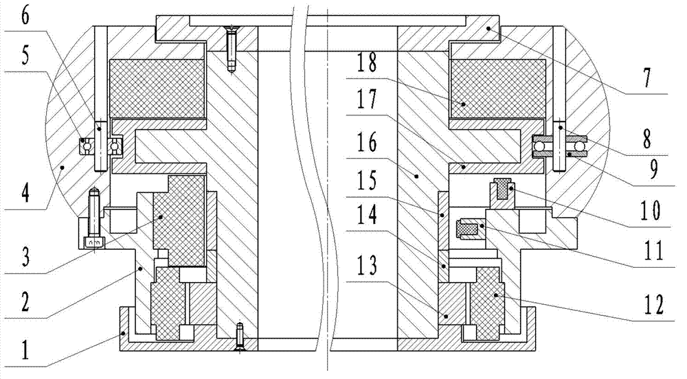
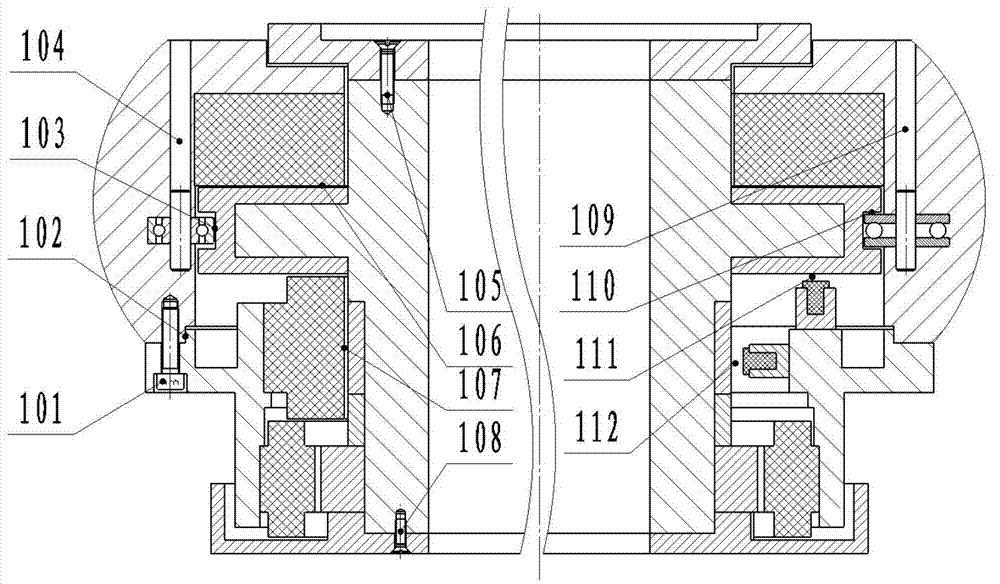
[0025] like figure 1 As shown, the azimuth drive support system structure of the inertial stable platform of the present invention includes: azimuth inner frame tray 1, azimuth lower outer frame 2, radial magnetic bearing stator 3, azimuth upper outer frame 4, deep groove ball bearing 5, deep groove ball Bearing shaft 6, azimuth inner frame cover plate 7, thrust bearing shaft 8, thrust bearing 9, axial magnetic bearing sensor 10, radial magnetic bearing sensor 11, azimuth motor stator 12, azimuth motor rotor 13, azimuth rotor spacer ring 14. Radial magnetic bearing rotor 15 , azimuth inner frame 16 , axial magnetic bearing rotor 17 ) and axial magnetic bearing stator 18 .

[0026] The azimuth inner frame tray 1, the azimuth lower outer frame 2, the upper azimuth outer frame 4, the azimuth inner frame cover plate 7 and the azimuth inner frame 16 constitute the structural part of the azimuth frame body; the azimuth motor stator 12 and the azimuth motor rotor 13 constitute Azimu...


PUM


Abstract

The invention relates to an azimuth drive support system structure of an inertially stabilized platform. The structure includes an azimuth frame body structure part composed of an azimuth inner frame and azimuth outer frames; an azimuth drive part composed of an azimuth motor stator and an azimuth motor rotor; an azimuth support part composed of a radial magnetic suspension bearing rotor, a radial magnetic suspension bearing stator, an axial magnetic suspension bearing rotor, and an axial magnetic suspension bearing stator; and a magnetic suspension bearing protection part composed of a deep groove ball bearing and a thrust bearing. The azimuth drive structure realizes control on the degree of freedom of azimuth direction, and isolates aircraft azimuth direction angular motion. The azimuth support structure realizes active suspension of the azimuth inner frame, enhances the bearing capacity, and can actively control azimuth frame torsion, thus effectively improving the platform stabilization accuracy. The deep groove ball bearing and the thrust bearing in the azimuth magnetic suspension protection structure are used for generating a fixed protective gap, thus avoiding azimuth magnetic suspension bearing pull-in. The invention simplifies the structure design of a heavy load inertially stabilized platform, improves the platform bearing capacity and stabilization accuracy, and is suitable for aerial remote sensing and target tracking.

Description

technical field [0001] The invention belongs to the technical field of aerial remote sensing, and is applicable to a large-load three-axis inertial stabilization platform system for aerial remote sensing with large load and small self-weight, and relates to an azimuth drive support system installed inside a large-load inertial stabilization platform, which can The free and precise adjustment of the azimuth direction is a complete supporting and driving integrated structure. It is a structural and method innovation of magnetic bearings in the field of inertial stabilization technology, and it can also be used in other mechanical mechanisms that require high-precision drive support, such as CNC lathes. Background technique [0002] The aerial remote sensing large-load inertial stabilization platform is one of the key equipment for airborne earth observation. Its function is to support the imaging load and isolate the attitude angle movement and external disturbance of the flig...

Claims


Application Information

Patent Timeline
Patent Type & Authority Patents(China)
IPC IPC(8): G01C21/18G05D1/08
Inventor 周向阳李贝房建成张建斌
Owner BEIHANG UNIV
Why Eureka
Try Eureka