
Iris wave-beam device capable of simulating infrared target

A technology of infrared target and aperture, applied in the field of optical test

Active Publication Date: 2013-07-24
武汉华中天勤防务技术有限公司
View PDF4 Cites 9 Cited by
  • Summary
  • Abstract
  • Description
  • Claims
  • Application Information

AI Technical Summary

Problems solved by technology

The prior art still lacks such a simulation test device for evaluating the effectiveness of photoelectric anti-jamming

Method used


Image

  • Iris wave-beam device capable of simulating infrared target
  • Iris wave-beam device capable of simulating infrared target

Examples


Embodiment 1

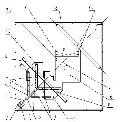
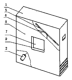
[0020] Such as figure 1 , 2 As shown, a variable aperture device for simulating an infrared target includes a box body 1, a motor 2 installed in the box body 1, a drive nut 3, a connecting rod 4, a guide rail 5 and a diaphragm plate 6, and Photoelectric operation control system; there are two diaphragms 6, each with a 90-degree notch 6.2 on each side; the two diaphragms 6 are stacked, and the 90-degree notch 6.2 is opposite to form a diaphragm that can be opened and narrowed. The "mouth"-shaped window 7; the main shaft of the motor 2 coincides with the "mouth"-shaped diagonal line of the window 7 along the long line, or is parallel; the two ends of the two diaphragms 6 are respectively connected to the two guide rails 5 through positioning pins 6.1. ; The two guide rails 5 are parallel and perpendicular to the axis of the motor spindle 2.1; the motor spindle 2.1 is a threaded rod on which a drive nut 3 is matched; the ends of the two diaphragms 6 close to the motor 1 move thr...

Embodiment 2

[0022] Example 2: The difference from the above-mentioned embodiment 1 is: the side length a of the 90-degree notch of the diaphragm plate 6 is equal to the maximum side length b of the square through hole of the window 7 plus the sum of the length c of the overlapping portion of the diaphragm plate 6, wherein the square through hole The maximum side length b is 100-300 mm. That is: the maximum side length b of the square through hole determines the size specification of the product of the present invention, the larger the selected value of the maximum side length b of the square through hole, the corresponding at least the aperture plate 6, the motor spindle 2.1, the connecting rod 4 and the guide rail 5 The length increases because of wanting to match, and casing 1 also should strengthen.

Embodiment 3

[0024] What is different from the above-mentioned embodiment 2 is a preferred embodiment. The maximum side length b of the square through hole is selected as 300 mm, and the size of the window 7 varies in the range of 0 to 300 mm in a square shape. This embodiment is a large iris device for simulating an infrared target.


PUM


Abstract

The invention relates to an iris wave-beam device capable of simulating an infrared target. The device is a movable mechanism which adjusts an imaging area of a thermal imager through adjustment of a clear aperture. The device comprises a box body, a motor, a transmission nut, a connecting rod, a guide rail, diaphragm pieces and a photoelectricity operation control system, wherein the motor, the transmission nut, the connecting rod, the guide rail and the diaphragm pieces are installed in the box body. The diaphragm pieces are two in number, and a side face of each diaphragm piece is provided with a 90-degree notch. The two diaphragm pieces are overlapped, and the 90-degree notches are oppositely arranged to form a square-shaped window which can spread and shrink. The device has the advantages that the diaphragm pieces are easy to machine, assemble and adjust, motion tracks are precise, operation is flexible, interference or inhibition in angle conversion of a motion component can be avoided, the window is precisely located, and uniform and precise motions of diaphragms can be guaranteed.

Description

technical field [0001] The invention relates to a variable aperture device for simulating an infrared target, which is a mechanism for gradually changing the imaging area of ​​a thermal imager by adjusting the aperture of the aperture, and is suitable for testing against equipped infrared thermal imagers. The image collected by the infrared thermal imager is an image with controllable size and radiation characteristics, which belongs to the technical field of optical experiments. Background technique [0002] Existing optoelectronic countermeasure equipment, such as weaponry and competitive equipment, uses various countermeasure mechanisms and multiple implementation approaches to protect the countermeasure equipment. With the wide application of photoelectric guidance equipment in countermeasures, various new systems and new mechanisms of photoelectric countermeasure equipment or technical measures are emerging. The evaluation of the effectiveness of specific countermeasur...

Claims


Application Information

Patent Timeline
IPC IPC(8): G01J5/08G02B26/02
Inventor 汤庆乐闫峰杨勇
Owner 武汉华中天勤防务技术有限公司
Learn More