SMT screen plate detection device
A detection device and stencil technology, applied in measurement devices, instruments, scientific instruments, etc., can solve the problems of low measurement accuracy, slow system response, low measurement efficiency, etc., to improve detection accuracy, high shaft accuracy, and reduce shaft The effect of friction in motion
- Summary
- Abstract
- Description
- Claims
- Application Information
AI Technical Summary
Problems solved by technology
Method used
Image
Examples
Embodiment 1
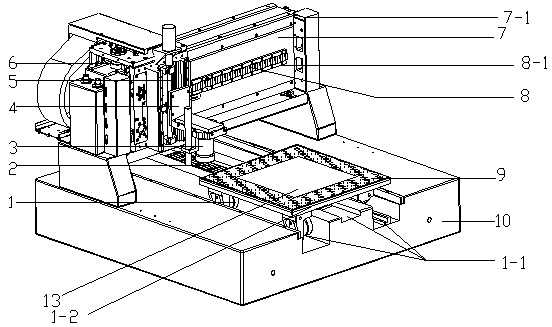
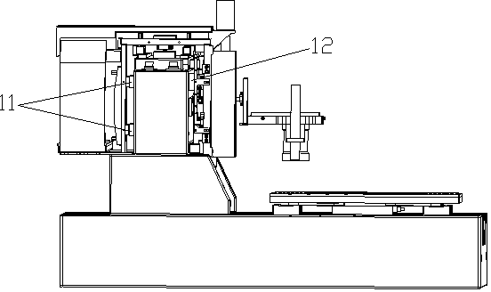
[0031] Such as Figure 1-2 Shown, a kind of SMT stencil detection device comprises Y-axis guiding air foot 1, Y-axis 1-1, Y-axis moving plate 1-2, Y-axis linear motor 2, precision measuring head 3, measuring head adjusting seat 4, Z-axis moving plate 5, X-axis support air foot 6, fixed beam 7, gantry frame 7-1, X-axis linear motor 8, X-axis 8-1, workpiece table 9, base platform 10, X-axis rear guide air foot 11 and X-axis front side guiding air foot 12. A Y-axis 1-1 is provided on the base platform 10, and a Y-axis moving plate 1-2 is arranged on the Y-axis 1-1. 1-2 moves back and forth along the Y-axis 1-1, the air flow groove structure is directly below the workpiece table 9, and the workpiece table 9 and the SMT screen 13 are adsorbed together by vacuuming. The bottom of the Y-axis moving plate 1-2 is provided with a Y-axis guiding air foot 1, and a Y-axis linear motor 2 is arranged on the Y-axis 1-1, so that the Y-axis moving plate 1-2 moves forward and backward along th...
Embodiment 2
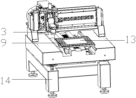
[0035] Such as image 3 Shown, a kind of SMT stencil detection device comprises Y-axis guiding air foot 1, Y-axis 1-1, Y-axis moving plate 1-2, Y-axis linear motor 2, precision measuring head 3, measuring head adjusting seat 4, Z-axis moving plate 5, X-axis support air foot 6, fixed beam 7, gantry frame 7-1, X-axis linear motor 8, X-axis 8-1, workpiece table 9, base platform 10, X-axis rear guide air foot 11. X-axis front guide air foot 12 and support seat 14. The support base 13 is located below the base platform 10 and is used to support the entire detection device. A Y-axis 1-1 is provided on the base platform 10, and a Y-axis moving plate 1-2 is arranged on the Y-axis 1-1. 1-2 moves back and forth along the Y-axis 1-1, the air flow groove structure is directly below the workpiece table 9, and the workpiece table 9 and the SMT screen 13 are adsorbed together by vacuuming. The bottom of the Y-axis moving plate 1-2 is provided with a Y-axis guiding air foot 1, and a Y-axis...
PUM
 Abstract
Description
Claims
Application Information
 - R&D
- Intellectual Property
- Life Sciences
- Materials
- Tech Scout
- Unparalleled Data Quality
- Higher Quality Content
- 60% Fewer Hallucinations
Browse by: Latest US Patents, China's latest patents, Technical Efficacy Thesaurus, Application Domain, Technology Topic, Popular Technical Reports.
© 2025 PatSnap. All rights reserved.Legal|Privacy policy|Modern Slavery Act Transparency Statement|Sitemap|About US| Contact US: help@patsnap.com


