
Detection method of switch cabinet measuring and controlling device of converting station

A technology of measurement and control devices and detection methods, which is applied in the direction of measuring devices, measuring electrical variables, instruments, etc., can solve the problems of tedious and time-consuming detection process, cannot be carried out at the same time, and delay test time, so as to save time and effort in the detection process and save debugging time , the effect of improving work efficiency

Active Publication Date: 2013-07-24
STATE GRID CORP OF CHINA +1
View PDF5 Cites 1 Cited by
  • Summary
  • Abstract
  • Description
  • Claims
  • Application Information

AI Technical Summary

Problems solved by technology

[0009] The disadvantages of this detection method are: 1. The procedure of installing a switch outdoors or in a high-voltage room is cumbersome and complicated. The test of the switch cabinet measurement and control device needs to wait for the installation to be completed, which cannot be carried out at the same time, which delays the test time.
2. The problem is found late, and once a problem occurs, the debugging time will be greatly delayed
3. Due to the huge system during the inspection, there are many possible fault points that need to be found, and they need to be checked one by one. The detection process is cumbersome and time-consuming, and there may be cross-faults in the switchgear measurement and control devices, cables or primary switches, and the fault location cannot be located and the number of fault points, causing maintenance personnel to misjudge
4. Once there is a problem with the measurement and control device of the switchgear, it is necessary to repeat steps 4 to 5 after the maintenance, which is a waste of time and low work efficiency

Method used


Image

  • Detection method of switch cabinet measuring and controlling device of converting station

Examples


Embodiment Construction

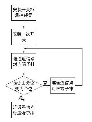
[0031] As shown in the figure, the detection method of the substation switch cabinet measurement and control device, the steps are as follows:

[0032] 1. Install the switchgear measurement and control device in the main control room of the substation.

[0033] 2. Install a primary switch outdoors or in a high-pressure room.

[0034] 3. Before or at the same time as installing the primary switch, connect the terminal row corresponding to the remote signal point of the switch cabinet measurement and control device through wires. In this embodiment, the specification of the wires is a 2.5mm cable.

[0035] 4. After the wires are connected, the switch cabinet measurement and control device shows that the switch has changed from the partial position to the close position, and the switch cabinet measurement and control device is working normally. If the switch cabinet measurement and control device is always in the partial position, it is considered that the measurement and control...


PUM

PropertyMeasurementUnit
Specificationaaaaaaaaaa

Abstract

Provided is a detection method of a switch cabinet measuring and controlling device of a converting station. The detection method of the switch cabinet measuring and controlling device of the converting station comprises the following steps that step 1, the switch cabinet measuring and controlling device is installed; step 2, a primary switch is installed; step 3, terminal strips which correspond to telecommand points of the switch cabinet measuring and controlling device are communicated through wires; step 4, when a switch cabinet measuring and controlling device display switch changes from an open position to a closed position, the switch cabinet measuring and controlling device is considered to normally work, and when the switch cabinet measuring and controlling device display switch keeps in an open-position state, the switch cabinet measuring and controlling device is considered to have a fault; step 5, once the switch cabinet measuring and controlling device is considered to have the fault, fault diagnosis needs to be carried out, and replacement of parts or depot repair needs to be carried out; step 6, the step 3, the step 4 and the step 5 are repeated until a detecting result is normal; step 7, the switch cabinet measuring and controlling device and the primary switch are connected; step 8, detection is carried out on the primary switch or a cable to judge whether a fault occurs; and step 9, detection and maintenance are carried out until the detecting result is normal. The detection method of the switch cabinet measuring and controlling device of the converting station has the advantages of being time-saving, labor-saving, high in working efficiency, simple in testing process, and capable of shortening a construction period.

Description

technical field [0001] The invention relates to a detection method for various substation switch cabinet measurement and control devices in a power system. Background technique [0002] In the power system, the staff need to remotely monitor the disconnection of each switch on the switch cabinet in real time. At present, the remote real-time monitoring of the switch cabinet is mostly realized through the switch cabinet measurement and control device. When installing the switch cabinet measurement and control device, it is necessary to ensure that its operation is stable and reliable. Therefore, it is necessary to test the switch cabinet measurement and control device in advance. The specific steps of the test are: [0003] 1. Install the switchgear measurement and control device in the main control room of the substation; [0004] 2. Install a primary switch outdoors or in a high-pressure room; [0005] 3. Lay the cable between the switch cabinet measurement and control d...

Claims


Application Information

Patent Timeline
IPC IPC(8): G01R35/00
Inventor 邱鹏孟祥博郭鸿鹏王蛟梁鹏张红吕峥韩飞赵明罗晓俭
Owner STATE GRID CORP OF CHINA
Learn More