
Drive battery device and motor vehicle with drive battery device

A technology for driving batteries and motor vehicles, applied in power units, electric power units, vehicle components, etc., can solve problems such as optimal use of no space, and achieve the effect of reducing overall complexity, weight, and complexity

Inactive Publication Date: 2017-04-12
FORD GLOBAL TECH LLC
View PDF3 Cites 0 Cited by
  • Summary
  • Abstract
  • Description
  • Claims
  • Application Information

AI Technical Summary

Problems solved by technology

[0007] The known drive battery arrangement neither offers the best possible protection nor the best use of space for the drive battery during a crash

Method used


Image

  • Drive battery device and motor vehicle with drive battery device
  • Drive battery device and motor vehicle with drive battery device
  • Drive battery device and motor vehicle with drive battery device

Examples


Embodiment Construction

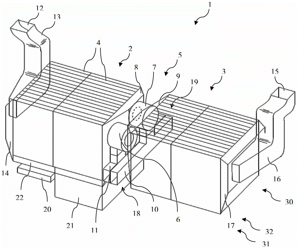
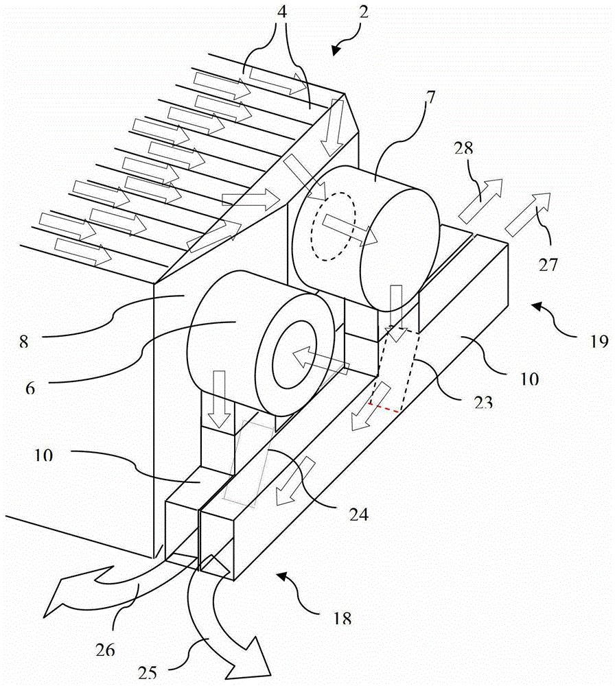
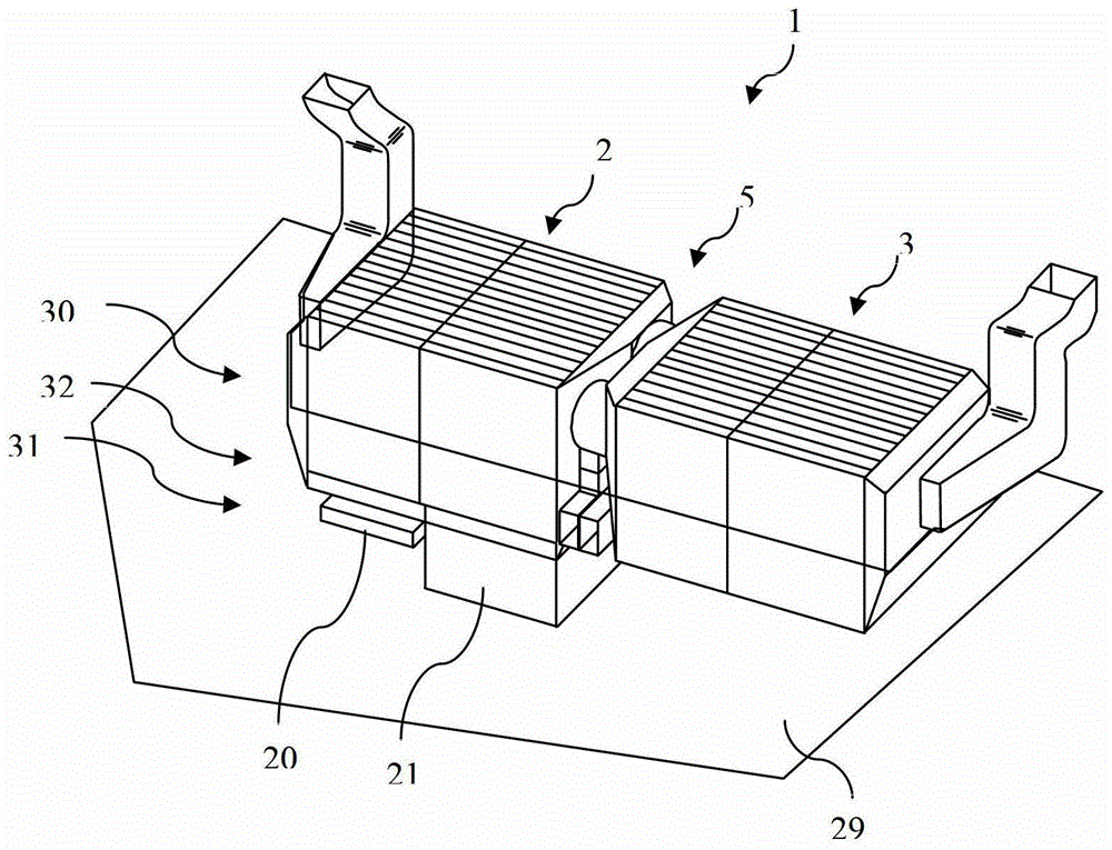
[0036] in figure 1 In the exemplary embodiment shown, the driving battery device 1 includes two driving batteries 2, 3, and each of the driving batteries 2, 3 may include a plurality of units 4. The two driving batteries 2, 3 are arranged in a manner of being spaced apart from each other, wherein the intermediate space between the driving batteries 2, 3 receives the fan device 5. The fan device 5 includes two fans 6, 7 and air collectors 8, 9 and exhaust pipes 10, 11. The air collector 8 is used to introduce air through the unit 4 of the first driving battery 2 in the most uniform manner, wherein the airflow is guided through the air inlet 12 and the air duct 13 and the air distributor 14 and delivered to the unit of the driving battery 2 4. The air heated while flowing through the unit 4 is introduced into the fan 7 by the air collector 8 and enters the exhaust pipe 10 through the fan 7. In order to cool the second driving battery 3, air is introduced by the fan 6 through th...


PUM


Abstract

A drive battery arrangement (1) according to the invention for a motor vehicle with a battery electric drive or a hybrid drive, comprising at least two drive batteries (2, 3) and a fan arrangement for cooling the drive batteries (2, 3) ( 5), wherein the fan arrangement (5) is arranged between at least two drive batteries (2, 3). The invention also relates to a motor vehicle with a drive battery arrangement.

Description

Technical field [0001] The present invention relates to a drive battery device for a motor vehicle with battery electric drive or hybrid drive and a motor vehicle equipped with this type of drive battery device. Background technique [0002] Motor vehicles with battery electric drive or hybrid drive (hybrid electric motor vehicles) require a drive battery capable of absorbing considerable energy in order to store the energy and release it in the form of electrical energy. The drive batteries in hybrid vehicles and battery electric vehicles are also described as "traction batteries." In order to reduce the resistance loss in the transmission line, usually this type of battery has a voltage higher than 100 volts. Since the driving battery generates heat when it is charged and / or discharged, it is necessary to cool it. For this purpose, multiple fans can be provided that can generate airflow through the drive battery and / or through or along the battery cell. Generally speaking, m...

Claims


Application Information

Patent Timeline
Patent Type & Authority Patents(China)
IPC IPC(8): H01M10/625H01M10/6563B60K1/04
CPCB60K1/04B60K2001/005B60K2001/0416B60K2001/0438H01M10/625H01M10/6563Y02E60/10
Inventor 马克·卢卡斯
Owner FORD GLOBAL TECH LLC
Learn More