
Power capacitor bank with capacity monitoring function

A power capacitor and capacity technology, applied in the measurement of resistance/reactance/impedance, measurement of electrical variables, instruments, etc., can solve the problems of difficult power user acceptance and wide-scale promotion and use, affecting the safety and stable operation of power equipment and components, etc. Achieve the effect of avoiding direct electrical connection, good practical use value, and avoiding major accidents

Inactive Publication Date: 2013-07-24
ZHEJIANG UNIV
View PDF6 Cites 9 Cited by
  • Summary
  • Abstract
  • Description
  • Claims
  • Application Information

AI Technical Summary

Problems solved by technology

[0004] However, the above-mentioned monitoring system is difficult to find the capacity change, fault trend and defect location of a single capacitor. Therefore, this monitoring system only detects the failure of the entire group of capacitors, and then performs power failure detection to find and troubleshoot the faulty capacitors one by one.
On the other hand, since this kind of monitoring system needs to install various voltage and current sensors on site and implement the secondary wiring of these sensors, this will inevitably lead to changes in the original high-voltage insulation design on site, thereby affecting the reliability of power equipment and components. Safe and Stable Operation
Therefore, it is difficult for this monitoring system to be recognized by power users and widely used

Method used


Image

  • Power capacitor bank with capacity monitoring function
  • Power capacitor bank with capacity monitoring function
  • Power capacitor bank with capacity monitoring function

Examples


Embodiment Construction

[0028] In order to describe the present invention more specifically, the technical solutions of the present invention will be described in detail below in conjunction with the accompanying drawings and specific embodiments.

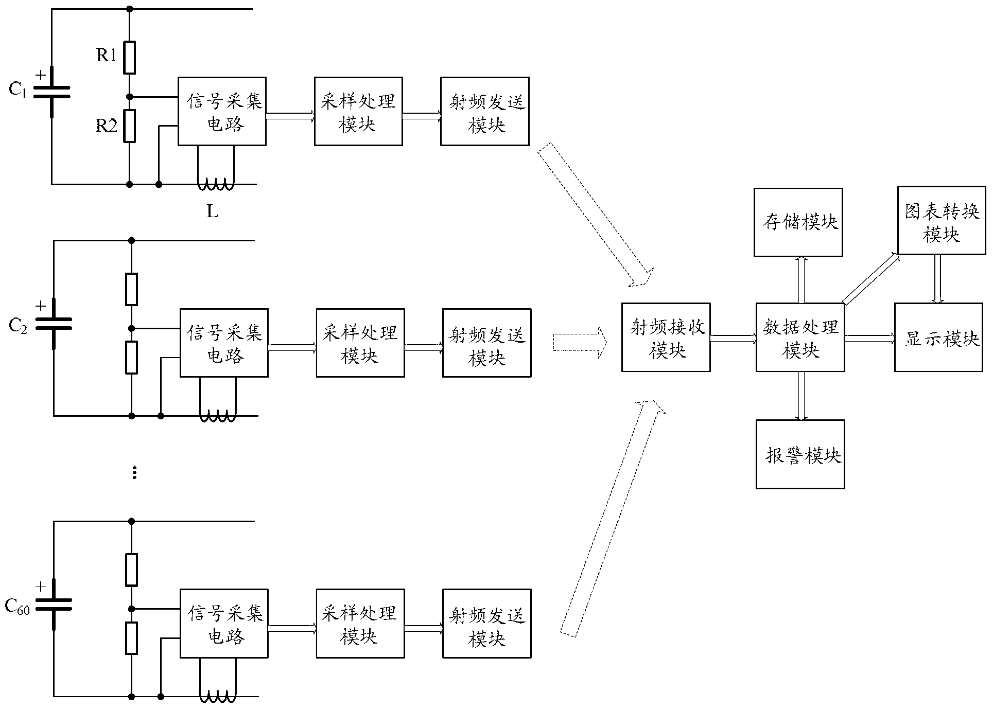
[0029] Such as figure 1 As shown, a power capacitor bank with capacity monitoring function includes 60 power capacitors C 1 ~C 60 and a main control processing unit, each power capacitor is connected with a voltage and current detection unit, the rated voltage of the power capacitor is 6000V, and the rated current is 50A.

[0030] The voltage and current detection unit includes a signal acquisition module, a sampling processing module and a radio frequency transmission module; where:

[0031] The signal acquisition module is used to collect the voltage signal at both ends of the power capacitor and the current signal flowing through the power capacitor; in this embodiment, the signal acquisition module is composed of a resistance voltage divider circuit...


PUM


Abstract

The invention discloses a power capacitor bank with a capacity monitoring function. The power capacitor bank comprises a plurality of power capacitors and a main control processing unit, wherein the power capacitors are connected with a voltage and current detection unit. The voltage and current detection unit comprises a signal collection module, a sampling processing module and a radio frequency sending module. The main control processing unit comprises a radio frequency receiving module, a data processing module and a display module. By means of real-time monitoring of short-term change characteristics and long-term change trends of capacity of each power capacitor, work conditions and failure phenomena of each power capacitor can be effectively diagnosed, so that effective measures can be taken in advance to remove hidden failure risks and serious accidents caused by spreading of failures are avoided. Additionally, a wireless radio frequency data transmission mode is adopted, direct electric connection between a high voltage side and a low voltage side is avoided, and good high voltage isolation functions and practical use values are achieved.

Description

technical field [0001] The invention belongs to the technical field of power system monitoring, and in particular relates to a power capacitor bank with capacity monitoring function. Background technique [0002] Power capacitors are important components of power systems, and are usually used for reactive power compensation, harmonic filtering, and power quality improvement in power systems. When the power capacitor is actually running in the power system, according to different voltage levels and the capacity to be compensated, usually multiple power capacitors are connected in series and parallel in various ways before they are put into actual operation. During the operation of the power capacitor bank connected in series and parallel, it is often damaged due to overload, overheating, harmonics, insulation breakdown, process defects, etc., and even burns or explodes in severe cases, which greatly threatens the safety of personal and equipment property. [0003] Before a m...

Claims


Application Information

Patent Timeline
Patent Type & Authority Applications(China)
IPC IPC(8): H02J13/00G01R27/26
CPCY04S40/126Y02E60/7853Y02E60/00
Inventor 陈隆道毛武斌陈铧璐
Owner ZHEJIANG UNIV
Learn More