
High-voltage IGBT converter module

A converter and high-voltage technology, applied in the direction of output power conversion devices, electrical components, cooling/ventilation/heating transformation, etc., can solve the problem of unreasonable layout of components, inconvenient disassembly and installation, and the circuit and structure of converter modules Changes and other issues to achieve the effect of wide output power range, convenient assembly and wiring, and convenient system design

Active Publication Date: 2012-11-28
ZHUZHOU CSR TIMES ELECTRIC CO LTD
View PDF6 Cites 18 Cited by
  • Summary
  • Abstract
  • Description
  • Claims
  • Application Information

AI Technical Summary

Problems solved by technology

Because the circuit structure and control of the two are different, generally the two cannot be interchanged or the interchangeability is poor;
[0006] (2) It is difficult to increase the power level
Therefore, if you want to increase the power level, you must use the components in series and parallel, which often leads to a large degree of modification in the circuit and structure of the converter;
[0007] (3) Inconvenient installation and maintenance
Due to the lack of modularization and convenience in structural design, many converters bring great inconvenience to installation and maintenance.
It is often necessary to dismantle many other components or components in order to repair one component or component, which not only has a large workload, but also has a serious impact on the reliability and overall life of the system
Because every time it is disassembled, the reliability of the corresponding components will be reduced. For example, the number of plugging and unplugging of general connectors is regulated. After this number is exceeded, the connector will no longer be reliable;
[0008] (4) The component layout is unreasonable and the electrical performance is affected
Due to the low degree of modularization and integration of general converters or the unreasonable layout of components, if low-inductance busbars are not used or related components are arranged too far away, the wiring inductance or line inductance will be too large, which will make the entire converter The electrical performance of the converter is affected, so that the potential of the converter cannot be fully exploited;
[0009] (5) Complex or poor cooling methods
One is directly installed on the IGBT component, so that the drive circuit lead inductance is the smallest, but on the converter module, its detection and maintenance are very difficult
Another way is to install the drive circuit in a space far away from the IGBT components for easy installation and replacement, but this will cause large lead inductance, which is not good for IGBT component drive and affects the safe operation of the converter module;
[0016] (3) Converter modules used for AC drives are generally divided into four-quadrant rectifier modules and inverter modules. Due to their different circuit structures and control methods, they are generally not interchangeable or have poor interchangeability. ;
[0017] (4) Limited by the technical level of power semiconductors, the previously developed series of converter modules mainly use 3300V or 1700V components, and the voltage levels corresponding to the intermediate DC circuit are 1500V and 750V. Therefore, if you want to increase the power level, you must adjust the components For series and parallel use, this often leads to a large degree of modification in the circuit and structure of the converter module, and the reliability is correspondingly reduced;
[0018] (5) Due to the complexity of the circuit and structure, it is very inconvenient to disassemble and install the converter module during inspection and maintenance, and special equipment tools are required for operation

Method used


Image

  • High-voltage IGBT converter module
  • High-voltage IGBT converter module
  • High-voltage IGBT converter module

Examples


Embodiment Construction

[0051] The following will clearly and completely describe the technical solutions in the embodiments of the present invention with reference to the accompanying drawings in the embodiments of the present invention. Obviously, the described embodiments are only part of the embodiments of the present invention, not all of them. Based on the embodiments of the present invention, all other embodiments obtained by persons of ordinary skill in the art without creative efforts fall within the protection scope of the present invention.

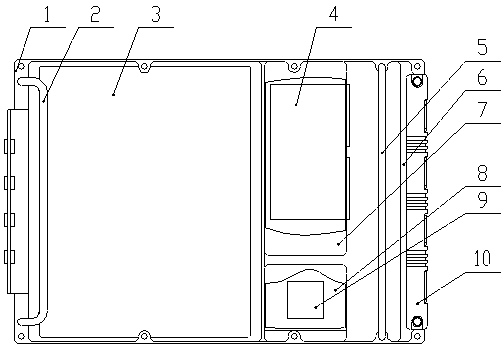
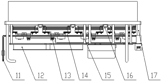
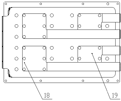
[0052] as attached figure 1 to attach Figure 5 As shown, a specific embodiment of a high-voltage IGBT converter module of the present invention is given, and the present invention will be further described below in conjunction with the drawings and specific embodiments.

[0053] as attached figure 1 And attached figure 2 Shown are the front view and top view of a specific embodiment of the high-voltage IGBT converter module of the present inventi...


PUM


Abstract

The invention discloses a high-voltage isolated gate bipolar transistor (IGBT) converter module, which adopts a drawer or vertical structure in which each component is mounted therein in a laminated way. A radiator is arranged at the bottom of the converter module; high-voltage IGBT components are arranged above the radiator and are uniformly arranged on the upper surface of the radiator; a high-voltage low-sensitivity busbar is arranged above the high-voltage IGBT components and is conductively connected with the IGBT components; an alternating current busbar is arranged above the horizontal side of the high-voltage low-sensitivity busbar and is conductively connected with the high-voltage IGBT components; a control box is arranged above the alternating current busbar and is fixed on the radiator; a gate driving power is arranged in a power box beside the control box; and a high-voltage gate driving circuit is arranged in a driving mounting box on the upper layer of the converter module. The converter module is simple in structure, attractive in appearance, safe and reliable, excellent in each performance and good in maintainability and interchangeability, and can meet the high-voltage large power occasions of intercity power train units, maglev trains, locomotives and the like.

Description

technical field [0001] The invention relates to the technical field of power electronic conversion, in particular to a new high-voltage IGBT (Isolated Gate Bipolar Transistor, insulated gate bipolar transistor) traction converter module structure design applied to rail vehicles. Background technique [0002] With the development of AC drive technology, the IGBT converter module, as an important part of the traction converter, is developing in the direction of modularization and serialization, and the application of IGBT converter modules is becoming more and more extensive. Some domestic companies have made relevant attempts, but due to problems such as immature technology, there is a big gap compared with similar foreign products. Therefore, the technical problem of IGBT converter modules has become one of the bottlenecks restricting the development of EMUs in my country. Due to the limitation of power semiconductor technology level and the imperfection of IGBT series and ...

Claims


Application Information

Patent Timeline
Patent Type & Authority Applications(China)
IPC IPC(8): H02M1/00H05K7/20
Inventor 忻力马伯乐陈燕平陈玉其杨光陈明翊杨涛欧阳柳唐威
Owner ZHUZHOU CSR TIMES ELECTRIC CO LTD
Learn More