All-optical high-voltage voltage transformer

A voltage transformer and high-voltage induction technology, applied in the field of all-optical high-voltage voltage transformer structure, can solve the problems of ferromagnetic resonance, complex insulation structure, introduction of optical path noise, etc., and achieve easy on-site use, simplified insulation structure, high anti-interference effect of ability

Active Publication Date: 2012-04-25
CHINA ELECTRIC POWER RES INST +1
View PDF5 Cites 18 Cited by
  • Summary
  • Abstract
  • Description
  • Claims
  • Application Information

AI Technical Summary

Problems solved by technology

This traditional voltage transformer has increasingly exposed its shortcomings in the safe operation of the power system, improving the accuracy of electric energy measurement and improving the automation of the power system: for example, it is difficult to insulate under high voltage and ultra-high voltage, and the insulation structure is complicated; The transformer connected to the power grid is equivalent to a nonlinear inductive load. Under certain conditions, ferromagnetic resonance may occur between it and the system capacitance, and there are ferromagnetic saturation and ferromagnetic resonance phenomena, resulting in waveform distortion and large linearity errors. ; The body of the transformer is filled with oil, and there is a potential danger of explosion; it has defects such as large volume and amazing quality
[0003] In the prior art, some optical voltage transformers are also disclosed. Compared with traditional electromagnetic voltage transformers, although they have signals transmitted by optical signals, thei

Method used


Image

  • All-optical high-voltage voltage transformer
  • All-optical high-voltage voltage transformer
  • All-optical high-voltage voltage transformer

Examples


Embodiment Construction

[0035] The all-optical high-voltage transformer of the present invention will be further described in detail below in conjunction with the accompanying drawings.

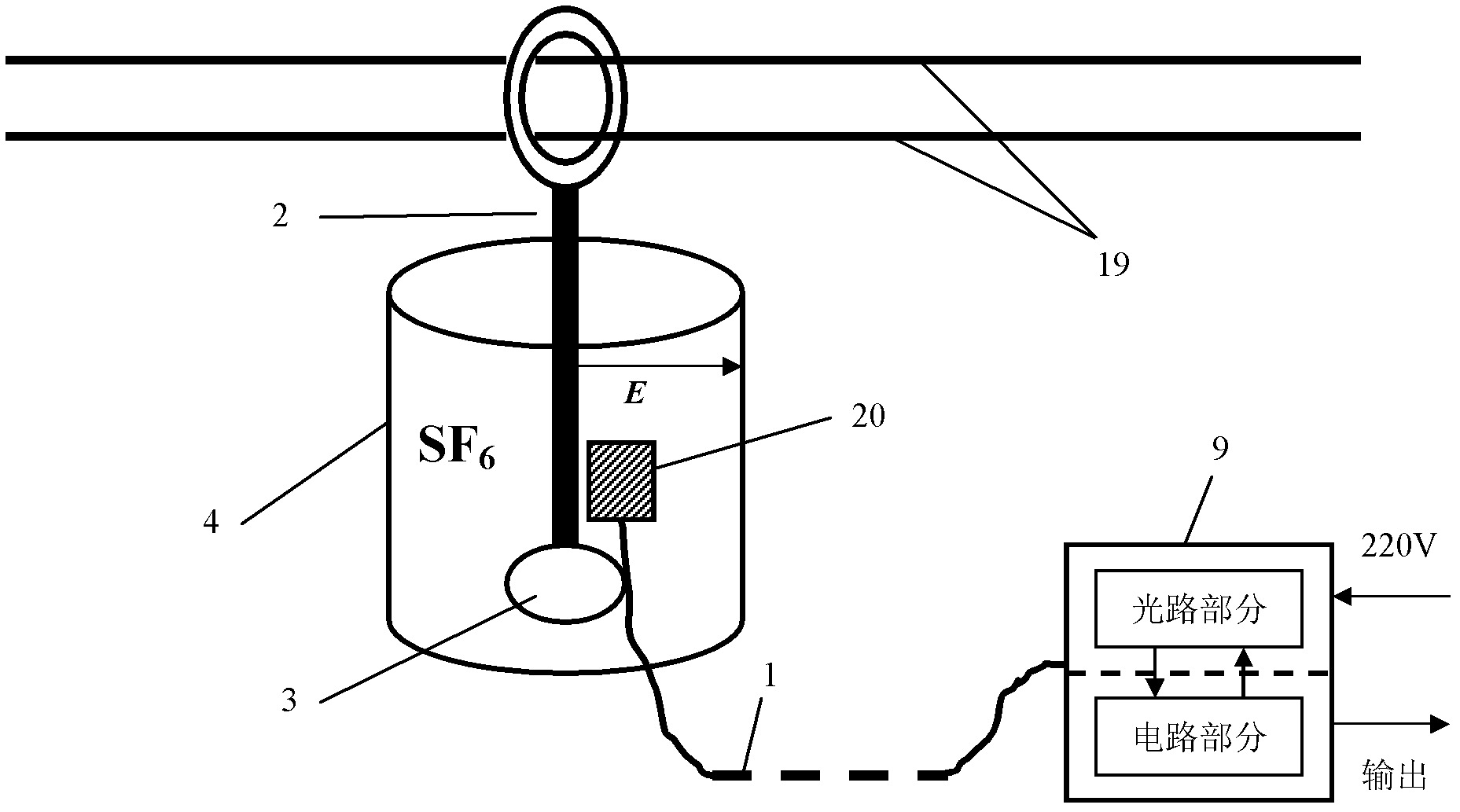
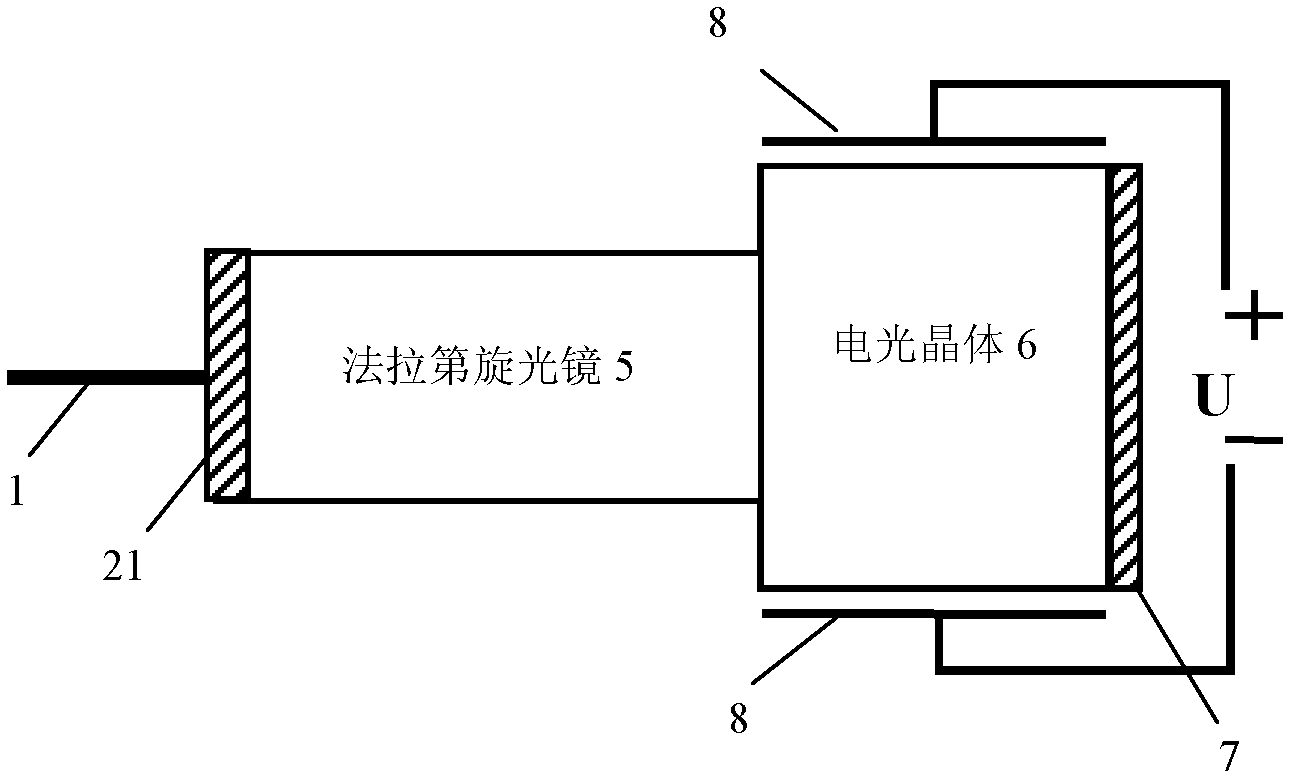
[0036] The all-optical high-voltage voltage transformer of the present invention is mainly composed of three parts: a sensing unit on the high-voltage side, a photoelectric unit on the low-voltage side, and a polarization-maintaining optical fiber connecting the sensing unit and the photoelectric unit.

[0037] Such as figure 1 As shown, the sensing unit includes a high voltage sensing device, a shielding insulation device and a sensing head.

[0038]The high-voltage induction device includes a metal guide rod 2 and a pressure equalizing ball 3, and the shielding and insulating device includes a sealed cylindrical shielding device 4 and SF filled in the shielding device for insulation. 6 gas. The metal guide rod 2 senses the high-voltage potential from the high-voltage line 18, and extends the lower part of the me...


PUM


Abstract

The invention brings forward an all-optical high-voltage voltage transformer. The voltage transformer comprises a high voltage induction device, a shielding insulation device, a sensing head and a photoelectric unit, wherein the high voltage induction device, a shielding insulation device, a sensing head are at a high voltage side and the photoelectric unit is at a low voltage side. Light that is emitted from a light source passes an optical path portion and is divided into two beams of orthogonal linearly polarized lights that are transmitted to the sensing head through a polarization maintaining fiber. Under the effect of an electric field, the sensing head enables the two beams of linearly polarized lights to generate a phase difference; and vibration directions of the two beams of linearly polarized lights are respectively rotated by 90 degrees, so that mode exchange of the two beams of the lights is realized. The two beams of linearly polarized lights that are returned from the sensing head is transmitted back to the optical path portion through the polarization maintaining fiber so as to carry out interference; and a circuit portion detects an interference light intensity signal and carries out signal processing; and then, a digital signal is formed and is output. According to the invention, the transformer enables completely isolation between a high voltage side and a low voltage side as well as has advantages of high security, strong anti-interference capability, small volume, light weight and simple structure and the like; and network and digitlization are easy to realize. Besides, a frequency response is wide, the dynamic scope is large and measurement precision is high.

Description

technical field [0001] The invention belongs to the field of voltage transformers, in particular to an all-optical high-voltage voltage transformer structure. Background technique [0002] With the development of science and technology, more and more power systems need to be in high-voltage or ultra-high-voltage environments. It is very unsafe to measure their voltage signals artificially, so voltage transformers play a very important role in power systems. It is one of the indispensable basic test equipment for power system monitoring. Usually, the primary side of the voltage transformer is connected to the primary system (for example: high-voltage line), and the secondary side is connected to measuring instruments, relay protection equipment, etc. At present, voltage transformers mainly include electromagnetic type and non-electromagnetic type (such as: electronic type, photoelectric type), the most widely used is the traditional electromagnetic induction voltage transform...

Claims


Application Information

Patent Timeline
IPC IPC(8): G01R15/18
CPCG01R15/24
Inventor 张朝阳雷林绪荆平温海燕陈祥训王成昊
Owner CHINA ELECTRIC POWER RES INST
Why Eureka
Try Eureka