Straight line and rotation coupling-out type piezoelectric driving device

A coupled output, piezoelectric drive technology, applied in the direction of piezoelectric effect/electrostrictive or magnetostrictive motors, generators/motors, electrical components, etc. installation, the difficulty of repairing at the same height, etc., to achieve the effect of simple structure, light weight and easy assembly

Active Publication Date: 2013-07-24
SHANGHAI INST OF TECHNICAL PHYSICS - CHINESE ACAD OF SCI
View PDF3 Cites 3 Cited by
  • Summary
  • Abstract
  • Description
  • Claims
  • Application Information

AI Technical Summary

Problems solved by technology

In the existing piezoelectric stack drive deflection actuators, only two-dimensional (X, Y direction) deflection mechanism can realize (Z direction) linear displacement output, which is divided into three piezoelectric stack drives and four piezoelectric stack drives in structure. There are two types of stacking drivers: the former requires decoupling control, which increases the complexity of the entire application system; the latter has four-point over-positioning, which makes it difficult to repair four points at the same height; The consistency of the displacement output characteristics of the piezoelectric stack used has a certain degree of requirement
So far, to achieve n-degree-of-freedom drive for piezoelectric stack drives, n or more piezoelectric stacks are required to complete the work together, and no piezoelectric drive device with both displacement output and rotation angle output in the axial direction has been found.

Method used


Image

  • Straight line and rotation coupling-out type piezoelectric driving device
  • Straight line and rotation coupling-out type piezoelectric driving device
  • Straight line and rotation coupling-out type piezoelectric driving device

Examples


Embodiment Construction

[0032] The specific embodiments of the present invention will be further described below in conjunction with the accompanying drawings.

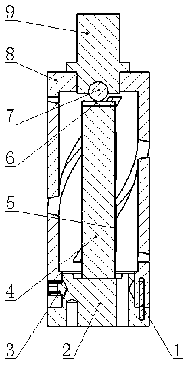
[0033] The set screw 1 is the standard part of M3×4 (vertex angle 120°) in GB / T78, the cylindrical pin 3 is the standard part of 1×8C1 in GB / T119.2; the piezoelectric stack 4 is the P-887.90 type of PI company Piezoelectric stack, the external dimensions are 7mm×7mm×36mm; the strain gauge 5 is BF350-3AA(9)N9 strain gauge produced by Zhonghang Electronic Measuring Instrument Co., Ltd.; the steel ball 7 is a standard steel ball with a diameter of 4mm, and the precision grade is G15.

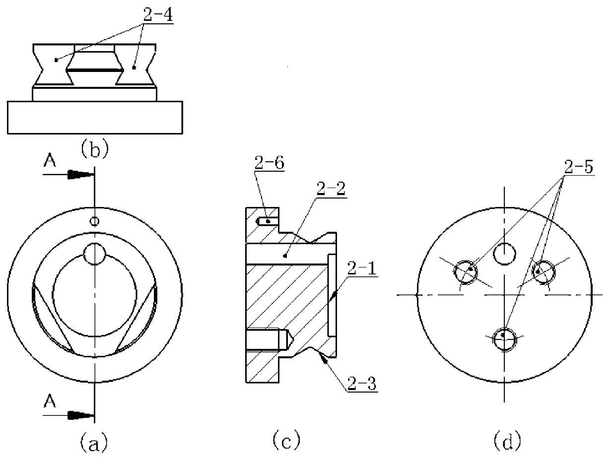
[0034] The structural material of the stacking mount 2 is 2Cr13 stainless steel. The upper cylinder has a diameter of 15.2mm and a height of 6.8mm. There is a flat-bottomed round hole with a depth of 1mm and a diameter of 10mm in the center of the upper end surface; Through hole; the side of the cylinder is 3.2mm away from the upper end surface, and there is an a...


PUM


Abstract

The invention discloses a straight line and rotation coupling-out type piezoelectric driving device which comprises a pile mounting seat, straight pins, a piezoelectric pile, strain foils, an invar sheet, a steel ball, a coupling-out component and an output shaft, wherein the strain foils are attached to the side surfaces of the piezoelectric pile, the bottom surface of the piezoelectric pile is adhered to the pile mounting seat, and the top surface of the piezoelectric pile is adhered to the invar sheet and is contacted with the steel ball inside an output shaft ball socket; the top of the coupling-out component is in interference nesting with the output shaft, and the bottom of the coupling-out component and the pile mounting seat are positioned with the straight pins and fixed with holding screws; after the piezoelectric pile applies voltage, the output shaft and the top of the coupling-out component are pushed to extend together along the axial direction; and because of the deformation coupling characteristics of the coupling-out component, the top of the coupling-out component and the output shaft rotate with a certain angle around the axial direction at the same time, and the angle is in direct proportion to the axial elongation. Output of straight line and rotary motion can be carried out in the axial direction at the same time, and the device has the advantages of being simple in structure, easy to control, large in angle rotation range, and high in displacement and angle rotation precision.

Description

technical field [0001] The invention relates to a piezoelectric micro-displacement and micro-angle driving device, in particular to a driving device in which a single piezoelectric stack drives a flexible structure to realize axial micro-displacement and micro-rotation angle coupling output. Background technique [0002] The piezoelectric stack has high displacement precision and fast response speed, and has been widely used in high-precision displacement platforms, machining accuracy compensation devices, and deflection actuators. The high-precision displacement platform and processing compensation device use the displacement characteristics of the piezoelectric stack to generate equal, enlarged or reduced displacement output in the original direction or other directions through the deformation of the thin-walled structure or the hinge structure; the deflection actuator mainly uses the hinge structure, using the principle of leverage to convert the linear displacement of th...

Claims


Application Information

Patent Timeline
Patent Type & Authority Applications(China)
IPC IPC(8): H02N2/06H02N2/14
Inventor 周辉姜紫庆郁洪轩周成林贾建军
Owner SHANGHAI INST OF TECHNICAL PHYSICS - CHINESE ACAD OF SCI
Why Eureka
Try Eureka