Cast rod locating cutting device

A technology for positioning cutting and casting rods, which is applied in the field of short casting rod devices and casting rod positioning and cutting devices. The effect of returning to the furnace and increasing the utilization rate

Inactive Publication Date: 2013-07-31
无锡海特铝业有限公司
View PDF0 Cites 5 Cited by
  • Summary
  • Abstract
  • Description
  • Claims
  • Application Information

AI Technical Summary

Problems solved by technology

The main problem is that the short material head of the part that does not make up the material cannot be separated and utilized, which reduces the utilization rate of the long cast rod

Method used


Image

  • Cast rod locating cutting device
  • Cast rod locating cutting device
  • Cast rod locating cutting device

Examples


Embodiment Construction

[0011] The present invention will be further described below in conjunction with specific drawings and embodiments.

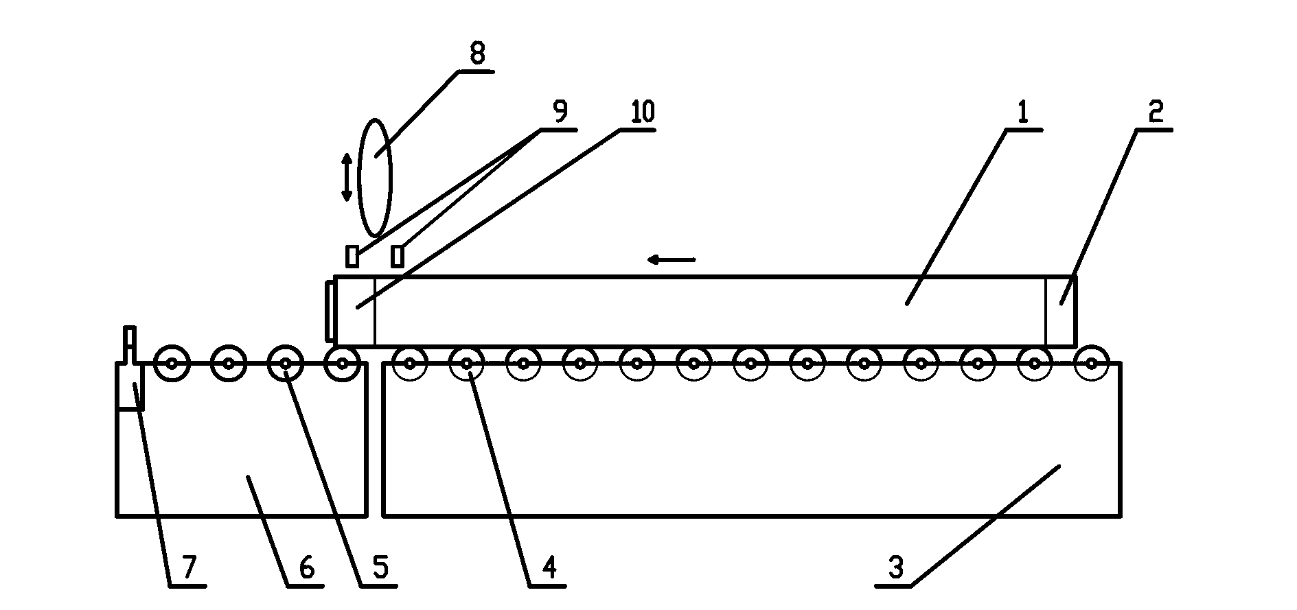
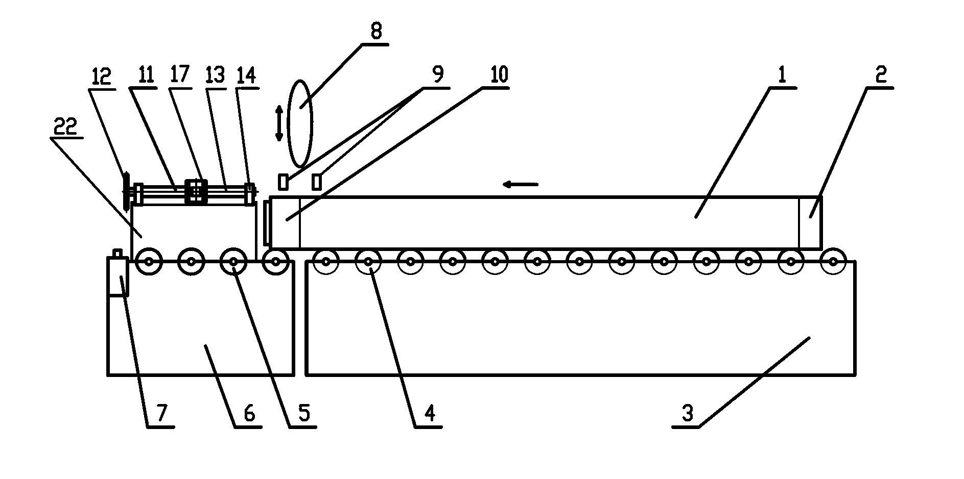
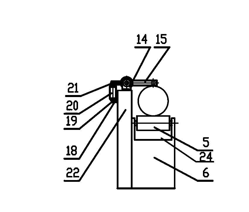
[0012] Such as Figure 1~4 As shown, it includes long casting rod 1, tail waste area 2, long material transmission table 3, long material transmission wheel 4, short material transmission wheel 5, short material transmission table 6, positioning rod 7, cutting saw blade 8, left and right double pressure Claw 9, head waste area 10, short positioning device 11, hand wheel 12, screw shaft 13, bearing with seat 14, short positioning swing arm 15, bushing 16, lock nut 17, oil cylinder support 18, the first A pin 19, a hydraulic cylinder 20, a second pin 21, a frame 22, a connecting rod 23, a groove 24, and the like.

[0013] Such as Figure 2~4 As shown, the present invention is a casting rod positioning and cutting device. The frame 22 is arranged at the rear part of the short material transfer table 6, and the short material transfer table 6 is placed at the fro...


PUM


Abstract

The invention belongs to the technical field of metal rod processing, relates to a device for cutting a long cast rod into short cast rods with needed lengths, and in particular relates to a cast rod locating cutting device. A short material conveying table and a long material conveying table form a conveying platform, a short locating unit is arranged above the short material conveying table and comprises a screw shaft and a short locating swing arm, the short locating swing arm is rotatably arranged on the screw shaft through a liner bushing and is locked on the two end faces of the liner bushing respectively through locking nuts, and the screw shaft is mounted on a bearing seat on a rack through a bearing. The cutting device can achieve effective separation of a short stub rod at a non-material gathering part of the cast rod from tail waste, and can effectively improve the utilization rate of the long cast rod and reduce return scrap.

Description

technical field [0001] The invention belongs to the technical field of metal rod body processing, and relates to a device for cutting long cast rods into short cast rods of required length, in particular to a cast rod positioning and cutting device. Background technique [0002] Common devices for cutting cast rods (such as figure 1 ), which is used to cut the whole long cast rod 1 (including the head waste area 10 and the tail waste area 2) into short cast rods of fixed length as required. When working, first place the long casting rod 1 horizontally on the long material transmission wheel 4 on the upper end surface of the long material transmission table 3, and manually push the long casting rod 1 to move on the long material transmission wheel 4, so that the head of the long casting rod 1 is waste The area 10 is placed under the left and right double pressure jaws 9. Now start the cutting machine, manually adjust the cutting saw blade 8 to cut off the head waste area 10 ...

Claims


Application Information

Patent Timeline
Patent Type & Authority Applications(China)
IPC IPC(8): B23D47/04
Inventor 植万宁
Owner 无锡海特铝业有限公司
Why Eureka
Try Eureka