Knitting tool block and method for creating same

A loop-forming tool and bar technology are used in textiles, papermaking, knitting, warp knitting and other directions to achieve the effect of low cost

Inactive Publication Date: 2013-07-31
KARL MAYER TEXTILMASCHFAB GMBH
View PDF10 Cites 3 Cited by
  • Summary
  • Abstract
  • Description
  • Claims
  • Application Information

AI Technical Summary

Problems solved by technology

However, associated with this is the risk that the slotted ...

Method used


Image

  • Knitting tool block and method for creating same
  • Knitting tool block and method for creating same

Examples


Embodiment Construction

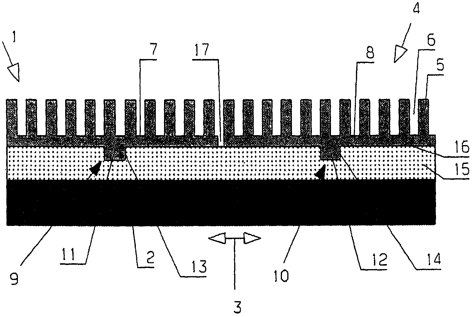
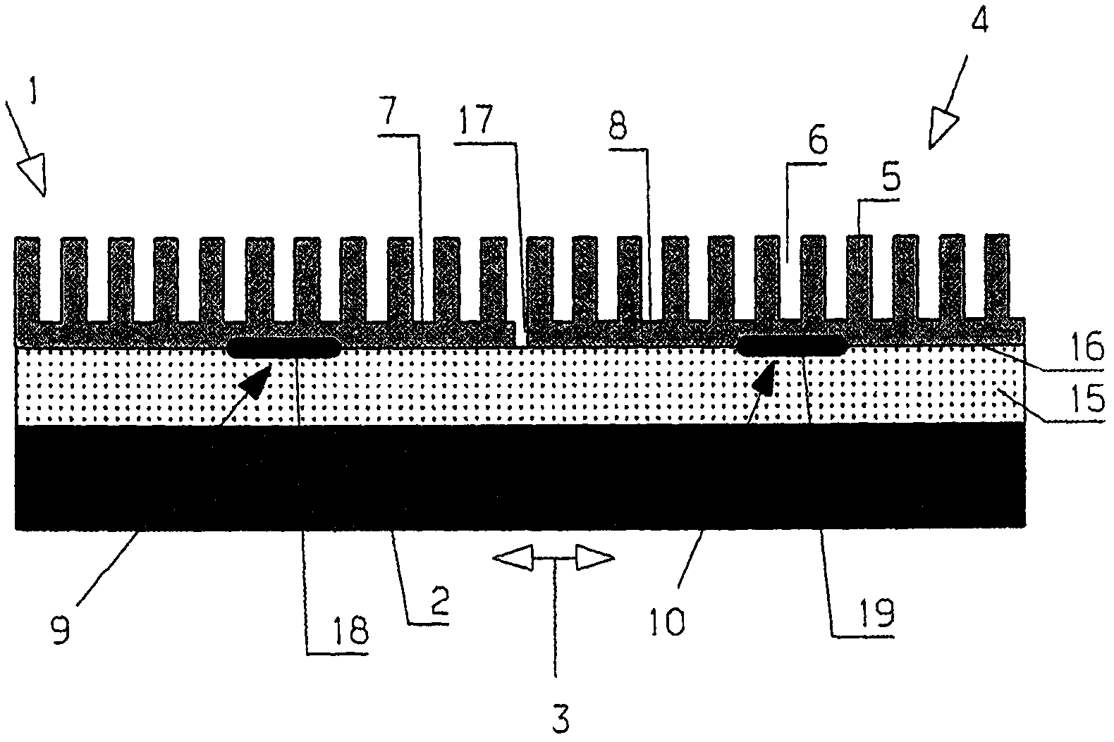
[0032] figure 1 Shown is a loop forming tool bar 1 with a body 2, which is formed from carbon fiber reinforced plastic. The body 2 has a longitudinal direction, which is indicated by the double arrow 3 . The body 2 may well have a length of several meters in the longitudinal direction. Accordingly, only a section of the looper bar is shown. The drawings are not to scale.

[0033] Such looping tool bars are used to similarly move groups of looping tools during the weaving process. Knitting tools may involve knitting needles, guide needles, loop sinkers and the like.

[0034] For receiving the looping tool, a looping tool holder 4 is provided which has a plurality of webs 5 and grooves 6 next to each other in the longitudinal direction 3 . The groove 6 serves to accommodate a loop forming tool, not shown in detail. The width of the groove 6 corresponds in the longitudinal direction to the thickness of the loop forming tool. In order to be able to insert the looping tool i...


PUM


Abstract

The bar (1) has a knitting tool receiver (4) attached at a body (2) and divided into multiple segments (7, 8) in a longitudinal direction (3), where each segment is fixed at the body in individual positions (9, 10) in the longitudinal direction by form closure. The knitting tool receiver comprises grooves (6) and a partition line (17) between the adjacent segments at edges of the grooves. The body comprises recesses (13, 14), where projections (11, 12) of the segments project into the recesses. The segments are made of metal, a ceramic material or a plastic i.e. fiber reinforced plastic. An independent claim is also included for a method for manufacturing a knitting tool bar.

Description

technical field [0001] The invention relates to a loop forming tool bar with a body having a longitudinal direction and a loop forming tool receptacle fastened to the body. Background technique [0002] Such a looping tool bar is known, for example, from DE 103 48 557 B3. [0003] Knitting machines typically have multiple loop forming tool bars. A looping tool is fixed at each looping tool bar. In general, "loop-forming tools" are to be understood as meaning all tools which take part in the loop-forming process during weaving. Examples of this include knitting needles, legenadels, loop sinkers, terry sinkers, and the like. [0004] Knitting machines often have a working width of several meters. Within this working width, the loop forming tools must be arranged at a defined spacing. This distance must also be maintained during operation in order to prevent collisions of different loop forming tools. Herein lies the problem that the knitting machine is exposed to tempera...

Claims


Application Information

Patent Timeline
IPC IPC(8): D04B27/24
CPCD04B27/24D04B27/06
Inventor G·舒勒S·考夫霍尔德
Owner KARL MAYER TEXTILMASCHFAB GMBH
Why Eureka
Try Eureka