Oil-gas separation part structure

A technology for separating components and components, which is applied in the direction of separation methods, dispersed particle separation, variable capacity pump components, etc., can solve the problems of poor use effect, inability to completely separate oil and gas, and short passage paths, etc., and achieve simple structure, improve gas Liquid recirculation effect, effect of increasing gas recirculation path

Inactive Publication Date: 2013-07-31
SHANGHAI VACUUM PUMP WORKS
View PDF5 Cites 1 Cited by
  • Summary
  • Abstract
  • Description
  • Claims
  • Application Information

AI Technical Summary

Problems solved by technology

[0003] It can be seen from the prior art that the use effect of the oil-gas separation device used in the traditional vacuum pump and compressor is not good. Due to the short path of the air flow, the oil and gas cannot be completely separated, so it is still necessary to carry out the structure of the existing oil-gas separation device. further improvement

Method used


Image

  • Oil-gas separation part structure
  • Oil-gas separation part structure

Examples


Embodiment Construction

[0009] The present invention will be further described below in conjunction with the accompanying drawings and embodiments.

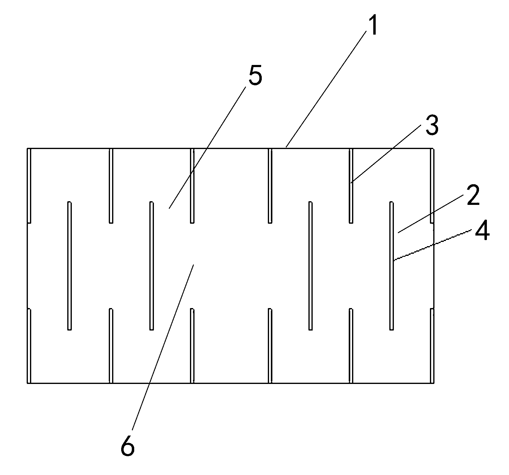
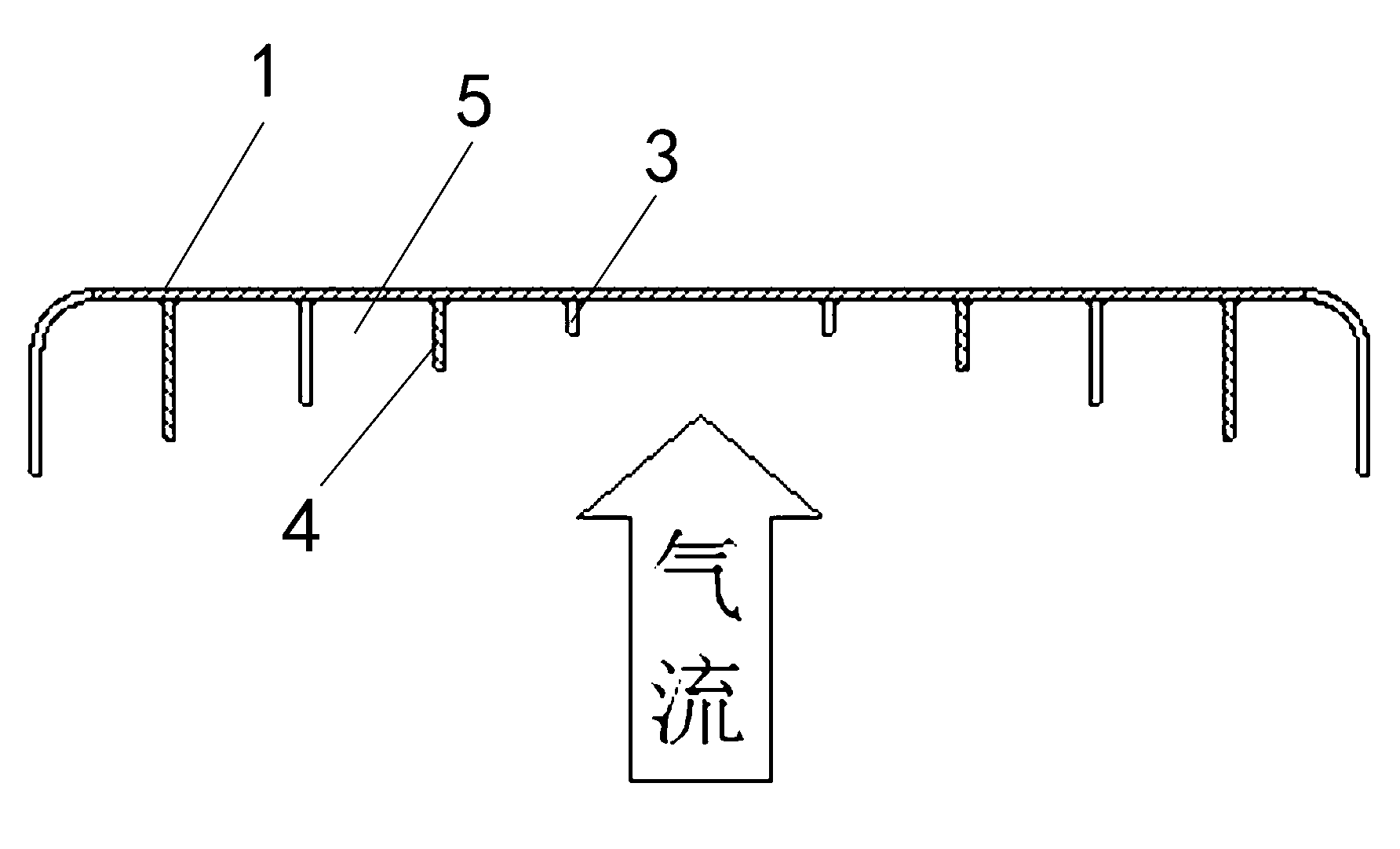
[0010] The invention discloses an oil-gas separation component structure, which includes a component body 1, which is different from the prior art in that several grid plates 2 are distributed on the surface of the component body 1 . The grid plate 2 is arranged perpendicular to the component body 1 .

[0011] In specific implementation, two short grid plates 3 are arranged on the side near the center of the component body 1, the two short grid plates 3 are located in a straight line, and the outer ends of the short grid plates 3 are fixedly connected to the edge wall of the component body 1, The inner ends of the short grids 3 are suspended, a gap 6 is formed between the suspended ends of the two short grids 3, and a long grid 4 is arranged at the component body 1 outside the two short grids 3, and the long grid 4 is connected to the above two A short...


PUM


Abstract

The invention discloses an oil-gas separation part structure which comprises a part body and is characterized in that a plurality of grid plates are distributed on the surface of the part body. The grid plate structures distributed in a staggered way are adopted, so that the gas reflux path is effectively added, the gas-liquid reflux effect is improved, oil fog drops are rebounded for multiple times and collide with each other to form larger oil drops, and the larger oil drops are collected on the surfaces of the grid plates; and the oil-gas separation part is high in separation efficiency, simple in structure and low in manufacturing cost, has a certain noise reduction effect, and is very good in practicality, easy to popularize and apply and suitable for all oil vacuum pumps and compressors.

Description

technical field [0001] The present invention relates to the technical field of oil-gas separation devices, in particular to a structure of oil-gas separation components, and in particular to the arrangement of grid plates of the oil-gas separation components. Background technique [0002] Reference document, patent application number: 201220041790.4, application date: 2012.02.09, patent applicant: Nantong Longying Vacuum Pump Industry Co., Ltd., this case discloses "a vacuum pump for oil and gas separation", including a pump body, characterized in that: the pump There is an air inlet at the bottom of the pump body, and a one-way valve is provided on the air inlet, and a filter device is provided on the periphery of the one-way valve on the air inlet, and a detachable oil return tank is provided on the periphery of the filter device at the bottom of the pump body. An oil-gas separation layer is provided on the upper side of the filter device inside the pump body, and an end c...

Claims


Application Information

Patent Timeline
Patent Type & Authority Applications(China)
IPC IPC(8): F04B39/00B01D45/08
Inventor 张健伟
Owner SHANGHAI VACUUM PUMP WORKS
Why Eureka
Try Eureka